8200-M628-O1 Rev A
212G/212GX Installation & Technical
Page 25
SETUP AND CALIBRATION, CONT.
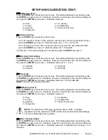
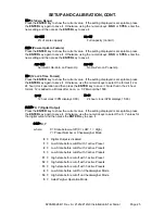
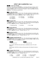
trL=
(4% Zero Range)
Press the
ENTER
key to show the current value. If the setting displayed is acceptable, press
the
ENTER
key again to save it. Otherwise, using the numeric keys,
0/NO
or
1/YES
, enter the
new setting and then press the
ENTER
key to save it.
trL
=YES
trL
=NO
4% of scale capacity
Full capacity (no limit)
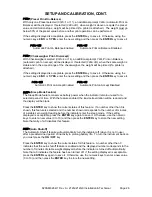
PUO=
(Power-Up Zero Feature)
Press the
ENTER
key to show the current value. If the setting displayed is acceptable, press
the
ENTER
key again to save it. Otherwise, using the numeric keys,
0/NO
or
1/YES
, enter the
new setting and then press the
ENTER
key to save it.
PUO
=YES
PUO
=NO
Automatic Re-Zero on Power-Up
No Re-Zero on Power-Up
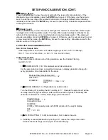
td=
(12 or 24 Time Format)
Press the
ENTER
key to show the current value. If the setting displayed is acceptable, press
the
ENTER
key again to save it. Otherwise, use the numeric keys to select the format (12 or
24 hour) clock operation and then press the
ENTER
key to save it. Note that in the 24 hour
format, 12 is added to all times after noon, i.e. 3 PM would be 1500.
td
=1
2
td=24
12 hour clock (3PM displays 3:00)
24 hour clock (3PM displays 15:00)
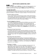
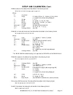
D oUt=
X, Y (Digital Output)
Press the
ENTER
key to show the current value. If the setting displayed is acceptable, press
the
ENTER
key again to save it. Otherwise, use the numeric keys to select the X, Y values for
the digital output and then press the
ENTER
key to save it.
d out=
X, Y
where:
X = State below cutoff (0 = LOW, 1 = High)
Y = Preset Number or Checkweigher Mode
0 =
Digital Output is disabled
1 =
Low State before cutoff with 1 active Preset
2 =
Low State before cutoff with 2 active Presets
3 =
Low State before cutoff with 3 active Presets
11 =
High state before cutoff with 1 active Preset
12 =
High state before cutoff with 2 active Presets
13 =
High state before cutoff with 3 active Presets
4 =
Low State before cutoff on Checkweigher Mode
14 =
High state before cutoff on Checkweigher Mode
5 =
Axle Weigher Operation Mode
Summary of Contents for 212G
Page 2: ...8200 M628 O1 Rev A 212G 212GX Installation Technical Page 2 ...
Page 10: ...8200 M628 O1 Rev A 212G 212GX Installation Technical Page 6 INSTALLATION CONT Figure No 2 ...
Page 27: ...8200 M628 O1 Rev A 212G 212GX Installation Technical Page 23 Lamp test on power up ...
Page 52: ...8200 M628 O1 Rev A 212G 212GX Installation Technical Page 48 ...


