17
P1
CTRL 30Vdc
CMN
CMN
FTC_I (N.C
)
TD (N.O
)
TA
(N.O
)
CMN
CMN
CMN
TC (N.O
)
TA
L (N.O
)
TB (N.C
)
CSP (N.C
)
LP
LS
OUT 30Vdc
M
V0
V1
V4 V3
BT
F2
BT
V2
21
20
19
18
17
16
15
14
13
12
11
10
9
8
7
6
5
4
Ant
Ant
P2
P3
L3
L1
L2
{
CN1
{
CN2
CN4
{
CN3
{
4
4
F1
15
15
F4
4
15
L11
L9
L7
L6
L10
L8
L5
1 2 3 4 5 6 7 8 9
ON
DS1
CSER
F3
3
2
1
CMN
EMRG
2
EMRG
1
D1
L4
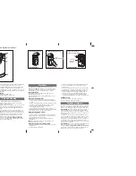
Terminal board connection
1
Common for the emergency buttons
2
EMRG 2
(NO contact) emergency manoeuvring button input
2
3
EMRG 1
(NO contact) emergency manoeuvring button input
1
4
Common for all inputs and outputs.
5
30 Vdc
output, powering external loads
(1)
.
6
Common for all inputs and outputs.
7
30 Vdc
controlled output, powering external loads
(1)
.
8
Common for all inputs and outputs.
9
LS
24 Vdc
3W
output for an indicator light.
10
LP
24 Vdc
output for warning lights.
25W
intermittent activation (50%),
12,5W
continuous activation
11 Common for all inputs and outputs.
12
FTCI
(NC contact) Safety and control devices in input (photocells invert
the travel direction when an obstruction is detected). Opening this contact
will provoke a travel direction inversion during closure due to the cutting
in of the safety device.
13
CSP
(NC contact) Safety buffer input). Opening this contact will provoke
a travel direction inversion of
10 cm
,
a pause of
3 minutes
, after which
the motor will continue moving in the original direction after a
10 second
preflashing period has elapsed.
14
TB
(NC contact) Stop button input (The opening of this contact interrupts
the cycle until a new movement command is given).
15 Common for all inputs and outputs.
16
TD
(NO contact) Dynamic button input
17
TAL
(NO contact) Limited opening button input
18
TC
(NO contact) Closing button input
19
TA
(NO contact) Opening button input
20 Outer conductor for radio receiver antenna
21 Inner conductor for radio receiver antenna (if an external antenna is fitted
use a coaxial cable
RG58
with an impedance of
50
7
).
Note
(1)
:
The total of the 2 external device outputs must not exceed
10 W.
ALL UNUSED NC CONTACTS MUST BE JUMPED.
If the
FTCI
input has been jumped the
FTCI
security device test must also be
DEACTIVATED$IP
OFF
)FYOUWANTTOACTIVATETHE
FTCI
test both the trans-
mission and receiver parts of the security devices must be connected to the
BINDINGPOSTMARKED
CTRL 30 Vdc
)FTHETESTISACTIVETHEREWILLBEASECOND
delay between the command transmission and movement of the gate.
Switch on the power and make sure that the indicator LEDS are in the following
condition (note: If the display is off you can press the
PROG
key to show the
status of the safety devices.
- L1
Power on
ON
- L2
Wrong battery connection
OFF
(2)
- L3
Transmitter code programming indicator
OFF
- L4
Battery charging
OFF
(3)
- L5
)NDICATORFORTHEBLOCKINGBUTTON
TB
ON
(4)
- L6
)NDICATORFORTHEINVERTINGPHOTOELECTRICCELLS
FTCI
ON
(4)
- L7
)NDICATORFORTHECONTACTSAFETYEDGE
CSP
ON
(4)
- L8
)NDICATORFORTHEOPENINGBUTTON
TA
OFF
- L9
)NDICATORFORTHEOPENINGBUTTON
TC
OFF
- L10
)NDICATORFORTHELIMITEDOPENINGBUTTON
TAL
OFF
- L11
)NDICATORFORTHEDYNAMICBUTTON
TD/CH1
OFF
Note
(2)
)FTHIS,%$IS
on
INVERTTHEBATTERYPOWERCABLES
immediately.
Note
(3)
4HIS,%$IS
on
WHENTHEBATTERYISCHARGED
Note
(4)
Check that the activation of the safety devices switches
the corresponding LEDS off.
If the
green power on LED doesn't light up
check the condition of the fuses
and the power cable connection at the transformer primary.
If
one or more of the safety LEDS do not light up
check the contacts of the
relative security devices and check that the unused safety device contacts
have been bridged.
10
CN1
Secondary Faston connection
24Vac
logic power supply
CN2
Secondary Faston connection motor circuit power supply
V2:0Vac
,
V3:20Vac
,
V4:30Vac
CN3
Battery Faston connection
CN4
Motor Faston connection
CSER
Serial connection (only for diagnostics)
D1
Six-segment LED display
DS1
Selection dip-switch
F1
15A
blade fuse
(1)
(motor power protection)
F2
4A
blade fuse
(1)
(
24V
circuit protection)
F3
15A
blade fuse
(1)
(motor power protection during battery
operation)
F4
4A
blade fuse
(1)
(
24V
circuit protection during battery opera-
tion)
Note
(1)
:
These are
automotive
type blade fuses
Summary of Contents for 100/SL324EBSB
Page 50: ...NOTES 50...