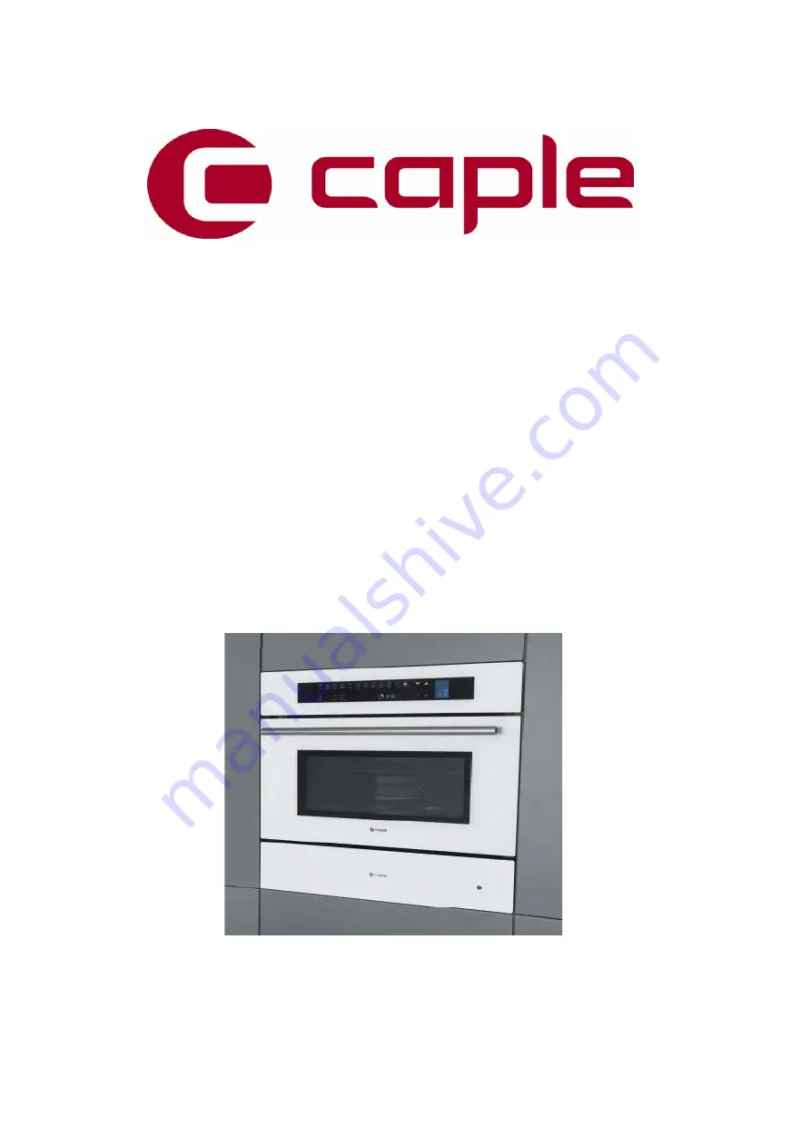
CM209WH
Caple Built In Combi MW/Grill 460mm
Technical information
Page 1: ...CM209WH Caple Built In Combi MW Grill 460mm Caple Built In Combi MW Grill 460mm Technical information...
Page 2: ...microwave fan auto settings 34 Litre capacity 6 Microwave power levels Thermostatic grill 60 Preset cooking recipes that can be customized Touch control timer and electronic clock Keep Warm function...
Page 3: ......
Page 4: ......
Page 5: ...LD 36 12111810 BOTTOM SHIELD 51 12200460 SHELF 53 12570170 CIRCULAR HEATING ELEMENT 1500W 54 12570180 GRILL HEATING ELEMENT 1500W 66 12105390 TRAY H20 INOX GN2 3 F45N 70 12380950 ADHESIVE GASKET 72 42...
Page 6: ...OTECTION 194 12112480 COMPONENT SUPPORT 195 12192440 AIR CONVEYOR F45N MAGNETRON 196 12193250 INNER DOOR HANDLE PROFILE 273 12380920 BUSHING FOR FLAT GLASS SWIVEL 275 12782058 MICROSWITCH N O F45 RIGH...
Page 7: ...CM209WH Caple built in Microwave Grill Service Manual...
Page 8: ...of energy emission 1 2 2 All repairs must be performed in such a manner that microwave energy emission is minimal 1 3 SPECIAL TOOLS MATERIALS 1 3 1 Tools 1 3 2 Necessary Measuring Instrument 2 TECHNI...
Page 9: ...TION 7 7 ROTATING DISH MOTOR SUBSTITUTION 7 8 MAGNETRON SUBSTITUTION 7 9 LOCK DOOR SWITCH SUBSTITUTION 7 10 DOOR GASKET SUBSTITUTION 7 11 SAFETY THERMOSTATS SUBSTITUTION 7 12 TRANSFORMER SUBSTITUTION...
Page 10: ...f the power is required to be on for electrical fault finding then extreme care should be taken not to make contact with electrical components other than with testing probes Ensure the oven is turned...
Page 11: ...not exceed one 1 inch per second In the area emitting the highest reading switch the meter to SLOW RESPONSE and take a reading for minimum of three 3 seconds We recommended the pattern outline shown b...
Page 12: ...3 socket extension bar z 7mm socket z 10 mm socket z 12mm socket z Flexible shaft socket extension z 1 and 2 Short Phillips Screw driver z Diagonal pliers z Long nose pliers z Flat blade screwdriver...
Page 13: ...Microwave oven Specifications 2 1 1 Oven Weight lbs Kg 86 39 2 1 2 Power rating TECHNICAL DATA MICROWAVE OVENS Electrical Ratings and Maximum Connected Load 220 240 Volts 50Hz Amperes Watts MHz CM109...
Page 14: ...Plate 2 2 1 Location The product serial number plate is located on the bottom profile trim 2 2 2 Model Serial Number The numbers printed on the plate contains the following information z Model z Seria...
Page 15: ...0 240 50 60 22 CL H Cooling Fan 220 240 50 60 30 CL H Rotating Plate 230 50 4 2 3 3 Electric Components Volts A Watts Note Door Lock Motor Switch 250 16 Lamp 230 25 Safety Thermostat s 250 16 T 210 Ca...
Page 16: ...ters are available in multifunction ovens They are combined together in different ways depending on the selected mode but the maximum power never overtakes 3200W GRILL ELEMENT 1500W at 230V RING ELEME...
Page 17: ...keys on the control panel must turn on on the display the lock icon is illuminated while the clock and temperature digits have to shows now the operator has a time of 2 3 sec to verify that all the li...
Page 18: ...00W Hold key the display shows 165 C hold key again to confirm the icons turn ON Rotating dish ON 6 Hold key the display shows the recipes window a hold key selecting Impostate hold to confirm it b ho...
Page 19: ...bers Faults N Temperature sensor disconnected or shorted Err 1 Door micro switch open Err 2 Electronic boards over temperature more than 85 C Err 3 Electronic boards sensor temperature damaged Err 4 F...
Page 20: ...thermostats are mounted in contact with the metal sheet The function of the safety thermostat is to protect the of the oven from overheating in the event of a malfunction of the cooling fan In the ev...
Page 21: ...ss Replace the sensor 7 14 ERROR 2 Door micro switch open Hardware failure Door micro switch broken Replace the door micro switch 7 9 ERROR 3 Electronic boards over temperature more than 85 C Overheat...
Page 22: ...ng other electrical appliances when you use the microwave oven Replace the fuses Short circuit Find the short circuit and remove it Check internal connections short circuit interruptions etc Microwave...
Page 23: ...hms High Voltage capacitor damaged Measure the resistance Terminal to terminal Wire leads removed Ohm meter scale Rx1000 Normal reading Momentarily indicates several ohms and then gradually returns to...
Page 24: ...rd Ohm meter scale Rx10000 7 16 Measure the continuity Wire leads removed Reverse Ohm meter scale Rx10000 Normal readings Infinite Abnormal reading continuity Safety Thermostat damaged Check for conti...
Page 25: ...roblems Anomaly Possible Cause Corrective Action section Fan does not run No power supply Bad connection Relay on power Board Check the connectors and the harness Replace the Control Board 7 18 Fan do...
Page 26: ...t wait to permit the capacitor discarding Troubleshooting guide 4 4 Convection Fan Problems Anomaly Possible Cause Corrective Action section Fan does not run No power supply Bad connection Relay of co...
Page 27: ...oubleshooting guide 4 5 Oven Light Problems Anomaly Possible Cause Corrective Action section The Oven lights are always OFF No power supply Bad connection The light not switching Check the connectors...
Page 28: ...seconds after the oven stops an electric charge remains in the high voltage capacitor When replacing or checking you must wait to permit the capacitor discarding Troubleshooting guide 4 6 Display Prob...
Page 29: ...tops an electric charge remains in the high voltage capacitor When replacing or checking you must wait to permit the capacitor discarding Troubleshooting guide 4 7 Door Hinge Problems Anomaly Possible...
Page 30: ...connection of the heating elements If there in not power on the heating elements check relays If the electronic control relay not switching replace the units 7 18 If there is not power on the heating...
Page 31: ...adjustment procedure 7 1 Oven removal 1 Disconnect the power supply cord 2 Open the door 3 Remove the screws shown in the pictures 4 Pull off the oven 5 Remove the oven by using the lateral handles L...
Page 32: ...cover 3 Disconnect the terminals on the fan 4 Remove the five screws on the fan and remove the fan 5 Replace the new one with the screws and connect the terminals 6 The connections must not be loose 7...
Page 33: ...oth hands and close the door then remove it 4 Hold firmly the door is heavy 5 Place the door in a convenient location To Replace Door 1 Insert the upper arms 2 of both hinges into the slots The recess...
Page 34: ...on the top fig 1 5 Remove the fan blade by using a 10mm socket fig 2 than remove the fan damaged by its three external screws fig 1 6 Disconnect the terminals on the fan in the rear side 7 Mount the n...
Page 35: ...t by removing the last two screws on the top fig 1 5 Remove ring element damaged by its screws fig 2 6 Disconnect the terminals on the heating element in the rear side 7 Mount the new ring heating ele...
Page 36: ...t the terminals 6 Unscrew the nuts fig 2 7 Than open the door to access to the heating element on the top of the cavity and unscrew the central screw fig 3 to remove the element damaged 8 Replace the...
Page 37: ...cloth to prevent scratching of the aesthetics 3 Remove the upper rear and lateral covers to access to dish motor 4 Disconnect the terminals 5 Remove the two screws to remove the motor damaged fig 2 6...
Page 38: ...oven structure unscrewing the four screws of its support fig 3 8 Replace the new one by reversing the previous steps Figure 1 NOTE When remove the magnetron be sure to install the magnetron gasket in...
Page 39: ...ect the terminals of micro switch 4 Remove the plastic support performing the two movements as showed in the figure 5 Replace the new one by reversing the previous steps 6 Connect the terminals 7 The...
Page 40: ...pull out the gasket by hands unhooking it by its 4 hooks on the corners 2 THE GASKET IS MADE BY A SPACIAL MATERIAL FOR MICROWAVE AND IT MUST BE FITTED PROPERLY 3 Replace with a new one by reversing t...
Page 41: ...Remove the internal components cover fig 1 by its six screws 4 Unscrew and disconnect the thermostat damaged fig 2 5 Replace the new one by reversing the previous steps 6 Connect the terminals The con...
Page 42: ...components cover fig 1 by its six screws 4 Disconnect the cable of transformer damaged and unscrew it by 4 base screws fig 2 5 Replace the new one by reversing the previous steps 6 Connect the termin...
Page 43: ...components cover fig 1 by its six screws 4 Disconnect the cable of condenser damaged and unscrew it by 2 base screws fig 2 5 Replace the new one by reversing the previous steps 6 Connect the terminal...
Page 44: ...ing a clamp make rounded the border to extract it fig 2 5 Disconnect the terminals fig 3 6 Replace the new one by reversing the previous steps 7 Connect the terminals and insert the temperature probe...
Page 45: ...cs 3 Unscrew the door external glass A Before to remove the hinges the hinge arm must be placed in the correct position following the steps 1 to 4 below 4 Remove the hinges unscrewing its screws B 5 T...
Page 46: ...components cover fig 1 by its six screws 4 Disconnect the cable of diode damaged and unscrew it by its base screw fig 2 5 Replace the new one by reversing the previous steps 6 Connect the terminals T...
Page 47: ...filter damaged and unscrew it by its base screws fig 1 4 Replace the new one by reversing the previous steps 5 NOTE for correct connection see the schematic label on filter 6 Connect the terminals The...
Page 48: ...upper cover 3 Disconnect the bad Control Board and remove it by its four plastic bracket fig 1 4 Replace the new one by reversing the previous steps 5 Connect the terminals The connections must not be...
Page 49: ...components cover fig 1 by its six screws 4 Open the fuse holder and remove the fuse damaged from the metal clamps fig 2 5 Replace the new one by reversing the previous steps 6 Connect the terminals Th...
Page 50: ...cloth to prevent scratching of the aesthetics 3 Remove the external glass from the door unscrewing two screws on the corner fig 1 4 Remove also the handle by its two screws to mount it on the new glas...
Page 51: ...e door unscrewing two screws on the corner fig 1 4 Remove also the four brackets on the corner to replace the glass fig 2 When it is changed an middle glass you must be sure that the face whit THERMO...
Page 52: ...the four brackets on the corner to remove the middle glass When it is changed or removed an middle glass you must be sure that the face whit THERMO REFLECTIVE printed it is towards the cavity fig 2 5...
Page 53: ...on the corner to remove the middle glass When it is changed or removed an middle glass you must be sure that the face whit THERMO REFLECTIVE printed it is towards the cavity fig 2 5 To remove the lab...
Page 54: ...hout disassembling the cable section 7 18 4 Substitute the glass damaged by removal of the four screws on metal brackets fig 1 5 Replace the new one by reversing the previous steps mounting also a new...
Page 55: ...ns to access to bulb as showed fig 1 4 Replace the new one by reversing the previous steps 5 The insulation around the lamp must be properly located it must not cover the lamp cavity holes 6 NOTE The...