54
l
Can BREE
ZE
Operating and Maintenance Cooling Unit Instructions 8-14 kW
www.canovate.com
l
l
P. +90 216 484 2222
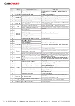
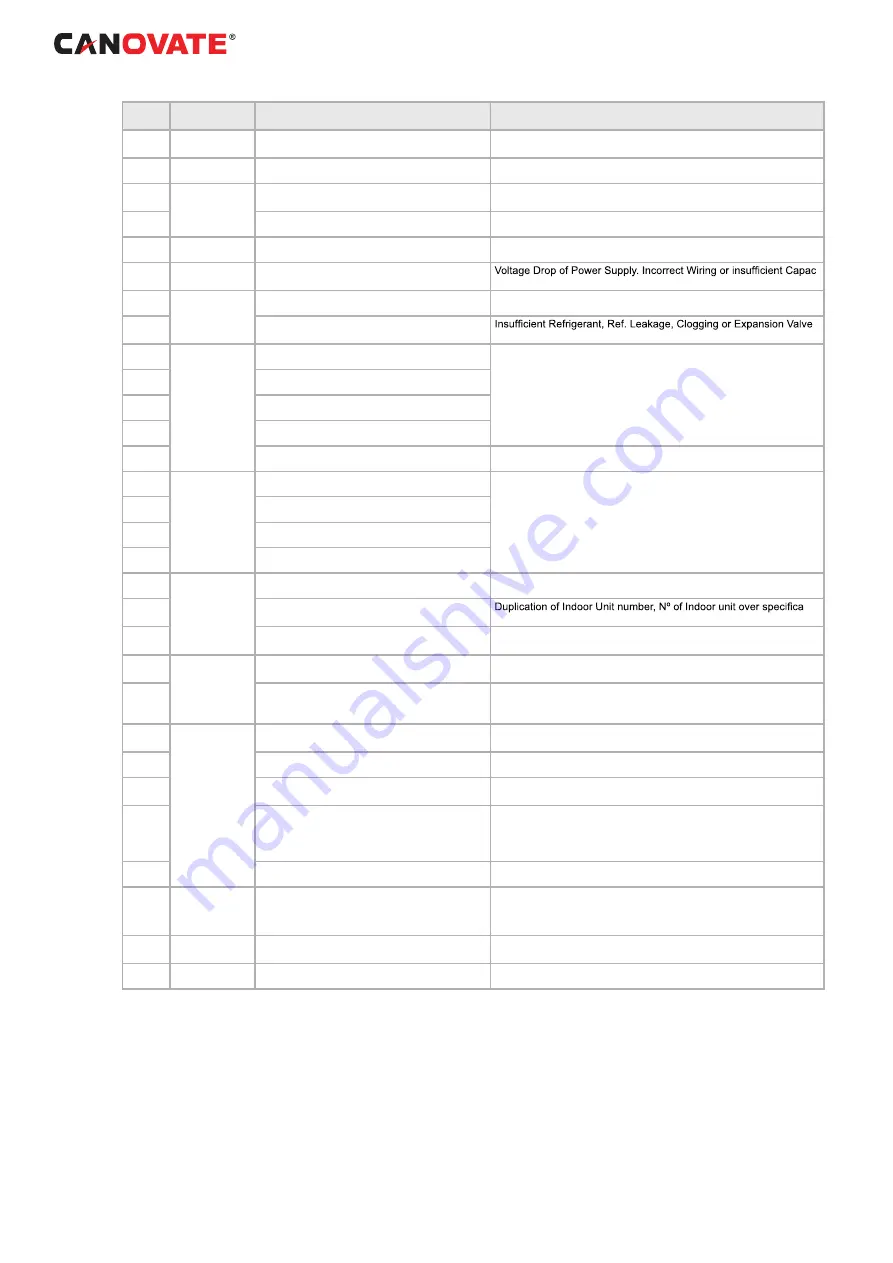
Code
No.
Category
Content of Abnormality
Leading Cause
01
Indoor Unit
Tripping of Protection Device
Failure of Fan Motor, Drain Discharge, PCB, Relay, Float Switch
Activated
02
Outdoor Unit
Tripping of Protection Device
Activation of PSH, Locked Motor
03
Transmission
Abnormality between Indoor (or Outdoor) and
Outdoor (or Indoor)
Incorrect Wiring, Failure of PCB, Tripping of Fuse, Power Supply
OFF
04
Abnormality between Inverter and Control PCB
Failure in Transmission between PCBs for Inverter
05
Power Supply
Abnormality power supply
Abnormal wave form of power supply.
06
Voltage Drop
Voltage Drop by Excessively Low or High Volt-
age to Outdoor Unit
-
ity of Power Supply Wiring
07
Cycle
Decrease in Discharge Gas Superheat
Excessive Refrigerant Charge, Expansion Valve Open Lock
08
Increase in Discharge Gas Temperature
Close Lock
11
Sensor on
Indoor Unit
Inlet Air Thermistor
Failure of Thermistor, Sensor, Connection.
12
Outlet Air Thermistor
13
Freeze Protection Thermistor
14
Gas Piping Thermistor
19
Tripping of Protection Device for Fan Motor
Failure of Fan Motor
20
Sensor on
Outdoor Unit
Compressor Thermistor
Failure of Thermistor, Sensor, Connection
(Incorrect Wiring, disconnecting wiring, breaking wire, short circuit)
21
High Pressure Sensor
22
Out+door Air Thermistor
24
Evaporating Thermistor
31
System
Incorrect Setting of Outdoor and Indoor Unit
Incorrect Setting of Capacity Code.
35
Incorrect Setting in Indoor Unit No.
-
tions.
38
Abnormality of Protective Circuit in Outdoor Unit
Failure of Indoor Unit PCB. Incorrect wiring. Connection to PCB in
Indoor Unit.
45
Pressure
Activation of High Pressure Increase Protection
Device
Overload Operation (Clogging, Short-Pass), Pipe Clogging, Exces-
sive Refrigerant, Inert Gas Mixing
47
Activation of Low Pressure Decrease Protection
Device
Stoppage by Excessively Decrease of evaporating Temperature
(Te < -35ºC) is activated 3 times in one hour, Locked Motor in Heat-
ing Operation.
48
Inverter
Activation of overload protection
Failure of IPM or PCB2, heat exchanger clogged, locked compres-
sor, EVI/EVO failure or overcharge.
51
Abnormality of Current Sensor for Inverter
Failure of Control PCB, Inverter Module.
53
Protection Activation of Transistor Module
Transistor Module Abnormality.
Failure of Compressor, clogging of Heat Exchanger.
54
Inverter Fin Temperature Increase
Abnormal Inverter Fin Thermistor.
Clogging of Heat Exchanger
Abnormal Outdoor Fan
55
Inverter Module Abnormality
Failure of Inverter Module.
57
Outdoor Fan
Fan Motor Abnormality
Disconnected wire of Incorrect wiring between Control PCB and
Inverter PCB.
Incorrect Wiring or Fan Motor Abnormality
b1
Indoor unit No.
setting
Incorrect address No. Setting or refrigerant
cycle
Over 64 indoor units setting by No. or indoor unit address.
EE
Compressor
Compressor protection alarm
Failure of compressor.

