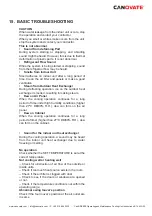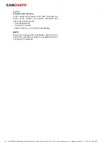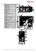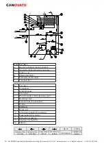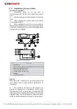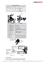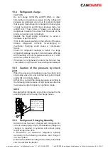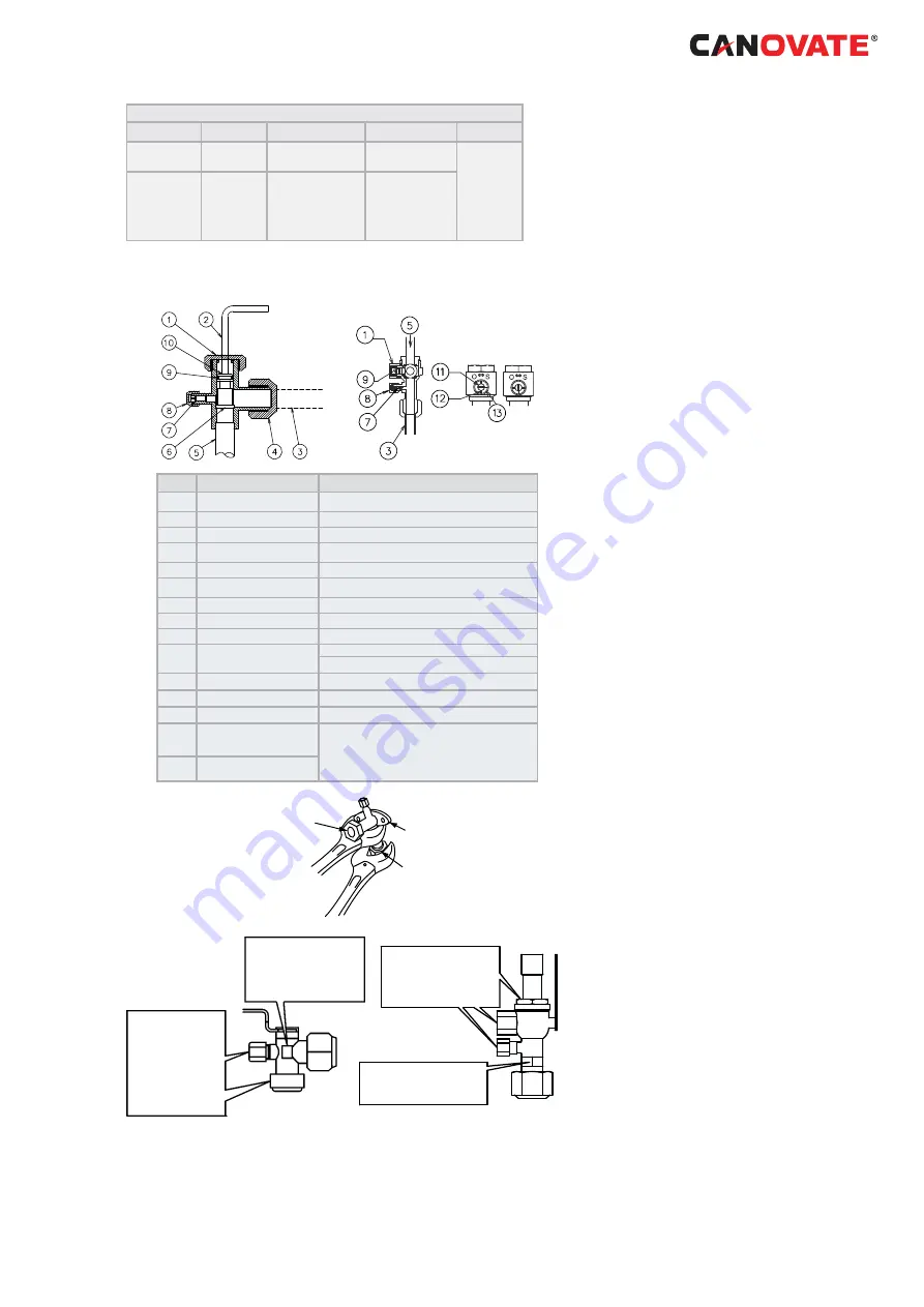
Tightening Torque (Nm)
1
2
3
4
Liquid valve
7-9
40
10HP: 60
33-42
14-18
Gas valve
9-11
80
8/10HP: 100
3HP: 33-42
4/5/6HP:
P=20-25
S/C=33-42
8/10HP:20-25
Spindle Type
Ball Type
(a)
(b)
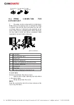
Nº
Description
Remarks
1
Cap
2
Allen wrench
Hex 4 mm
3
Refrigerant Piping
Field Supplied
4
Flare nut
5
Refrigerant Pressure
To Outdoor Unit
6
Seat Surface
Fully closed position
7
Check Joint
Only the charging those can be connected
8
Charge port cap
9
O-Ring
Rubber
10
Spindle valve
Open – Counterclockwise
Close – Clockwise
11
Shaft
12
Pin
13
Stopper
(a)
Closed
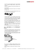
This valve is opened or closed with rotating 90
degrees at the ball valve part. Rotate the shaft
until the pin touches the stopper. Do not apply the
extra force. Use a slotted screwdriver to control
the shaft. Do not leave the ball valve partly ope
n
(b)
Opened
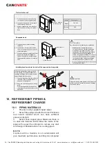
Do not apply two spanners
at this position. If applied,
leakage will occur.
Stop valve
(Spindle type)
Flare nut
Use two spanners
here for pipe con-
nection
Do not work with
two spanners
here.
Refrigerant
leakage shall
occur
Position to apply
spanners
Don not apply
two spanners
work here
Spindle type
Ball type
C A U T I O N
At
the
test
run,
fully
open
the
spindle
and
ball
stop
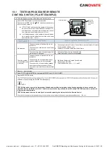
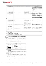
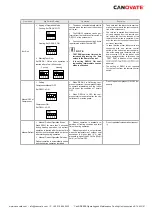
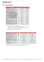
valve. If not fully opened, the devices will be damaged.
www.canovate.com
l
l
P. +90 216 484 2222
Can BREE
ZE
Operating and Maintenance Cooling Unit Instructions 8-14 kW
l
39

