www.canovate.com
l
l
P. +90 216 484 2222
Can BREE
ZE
Operating and Maintenance Cooling Unit Instructions 8-14 kW
l
17
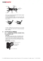
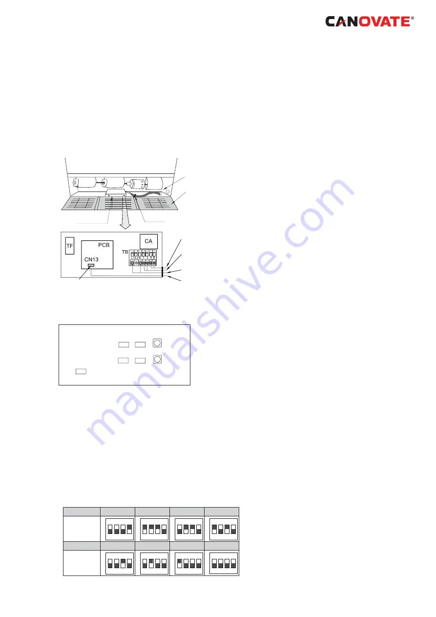
The electrical wiring connection for the indoor unit is
shown below.
1. Connect the cable of the remote control switch to
the terminals A and B in electrical box through the
connecting hole in the cabinet, as shown below.
2. Connect the power supply and ground wires to the
terminals in the electrical box.
3. Connect the wires between the indoor unit and the
outdoor unit to the terminals 1 and 2 in the electrical
box, as shown below:
Cord clamp
RCS (Optional)
Electrical Box
Grille
Knockout hole
for wirings
Transmission wires
Power wires
RCS (Optional)
Connector
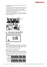
9.2
SETTINGS OF DIP SWITCHES
Quantity and Position of Dip Switches
Dips switches position is the following:
DSW6
DSW5
DSW4
DSW3
DSW7
RSW1
RSW2
CAUTION:
Before setting dips switches,
fi
rstly turn off power
source and set the position of the dips switches. If the
switches are set without turning off the power source,
the contents of the setting are invalid.
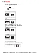
DSW3: Capacity Code Setting
No setting is required, due to setting before shipment.
This dip switch is utilized for setting the capacity code
which corresponds to the Horse Power of the indoor
unit.
HP
1.8
2.0
2.3
2.5
Setting
Position
ON
1 2 3 4
ON
1 2 3 4
ON
1 2 3 4
ON
1 2 3 4
3.0
4.0
5.0
6.0
Setting
Position
ON
1 2 3 4
ON
1 2 3 4
ON
1 2 3 4
ON
1 2 3 4

