


(3) LF / Eject Correction
After replacement of the feed roller, platen unit, LF / Eject encoder, encoder film, or logic board in repair servicing or in
refurbishment operation, perform the adjustment to maintain the optimal print image quality.
1) Print the LF / Eject correction pattern.
Click
LF/EJECT
of the Service Tool on the connected computer, select the paper source and the paper type, and print the
pattern. 5 sheets of paper will be used for the pattern printing.
- Paper source: Select either
Rear tray
or
Cassette
.
- Media type: Select one from
HR-101
,
GF-500/Office Planner
,
HP Bright White
, and
Canon
Extra/STEINBEIS
.
2) When printing is finished, the machine returns to be ready for selection of another function ("Service Mode Idle" is displayed
on the LCD).
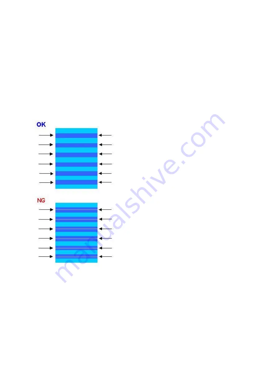
3) In the printout, determine the Pattern No. in which streaks or lines are the least noticeable for the LF check pattern and the Eject
check pattern respectively.
(LF Pattern No. 0 to 4, Eject Pattern No. 0 to 4)
4) Select and set the correction values.
In the
LF/EJECT Correction
section of the Service Tool, select the Pattern No. (from 0 to 4) determined in step 3) for
LF
and
EJECT
respectively, and click
Set
.
5) The selected LF and Eject correction values are written to the EEPROM, making the E-MIP correction value (which was set at
shipment from the production site) invalid.
Note: At the production site, the E-MIP correction, which is equivalent to the LF / Eject correction, is performed
using the special tool, and the E-MIP correction value is written to the EEPROM as the valid data.
When LF / Eject correction is performed, the LF / Eject correction values become valid instead of the E-MIP
correction value (thus, in the initial EEPROM information print, "LF = *" and "EJ = *" are printed, but the
selected values are printed after the LF / Eject correction).
49 / 64
Summary of Contents for PIXMA MX860 series
Page 8: ...5 64 ...
Page 30: ...6 Separate the scanner from the document feeder no screws 27 64 ...
Page 32: ...29 64 ...
Page 34: ...2 Remove the document feed cover eject tray and tray base 4 screws 31 64 ...
Page 36: ...4 Remove the LCD ass y no screws 5 Remove the panel board 10 screws 33 64 ...
Page 40: ...7 Remove the PE sensor board 5 screws 37 64 ...
Page 50: ... 2 Service Tool functions Service Tool screen Version 1 030 47 64 ...
Page 58: ...PTT parameter print sample for the MX860 Japan model 4 3 PTT Parameter Mode 55 64 ...
Page 65: ... 2 Service test print Service test print sample 62 64 ...
Page 66: ... 3 Ink absorber counter value print Print sample 4 6 Verification Items 63 64 ...
Page 74: ...REFERENCE PRINTER UNIT FIGURE 13 OPTION CONSUMABLES FIGURE 14 TOOL A 3 ...
Page 75: ...B PARTS LAYOUT PARTS LIST FIGURE 1 PACKING CONTENTS PRINT HEAD B 1 ...
Page 77: ...FIGURE 2 AC ADAPTER B 3 ...
Page 79: ...FIGURE 3 EXTERNAL COVERS SCANNER UNIT B 5 ...
Page 81: ...FIGURE 4 DOCUMENT PRESSURE PLATE UNIT B 7 ...
Page 83: ...FIGURE 5 OPERATION PANEL UNIT B 9 ...
Page 85: ...FIGURE 6 MAIN CASE UNIT FRONT DOOR UNIT B 11 ...
Page 87: ...FIGURE 7 BOTTOM CASE INK ABSORBER B 13 ...
Page 89: ...FIGURE 8 LOGIC BOARD ASS Y PE SENSOR BOARD ASS Y B 15 ...
Page 91: ...FIGURE 9 SHEET FEED UNIT B 17 ...
Page 93: ...FIGURE 10 CARRIAGE UNIT PRESSURE ROLLER UNIT B 19 ...
Page 95: ...FIGURE 11 PLATEN UNIT SPUR UNIT B 21 ...
Page 97: ...FIGURE 12 PURGE DRIVE SYSTEM UNIT SWITCH SYSTEM UNIT B 23 ...
Page 99: ...REFERENCE PRINTER UNIT B 25 ...
Page 100: ...C OPTION CONSUMABLES FIGURE 13 OPTION CONSUMABLES C 1 ...
Page 103: ...E TOOL FIGURE 14 TOOL E 1 ...


