


4-2. Service Mode
(1) Service mode operation procedures
Use the Service Tool on the connected computer.
1) Start the machine in the service mode.
i. With the machine power turned off, while pressing the Stop button, press and hold the ON button. (DO NOT release the
buttons.)
ii. When the Power LED lights in green, while holding the ON button, release the Stop button. (DO NOT release the
ON button.)
iii. While holding the ON button, press the Stop button 2 times, and then release both the ON and Stop buttons. (Each
time the Stop button is pressed, the Alarm and Power LEDs light alternately, Alarm in orange and Power in
green, starting with Alarm LED.)
- Without the scanner (connect the operation panel unit);
While holding the ON button, press the Stop button 3 times, and then release both the ON and Stop buttons. (Each time
the Stop button is pressed, the Alarm and Power LEDs light alternately, Alarm in orange and Power in green.)
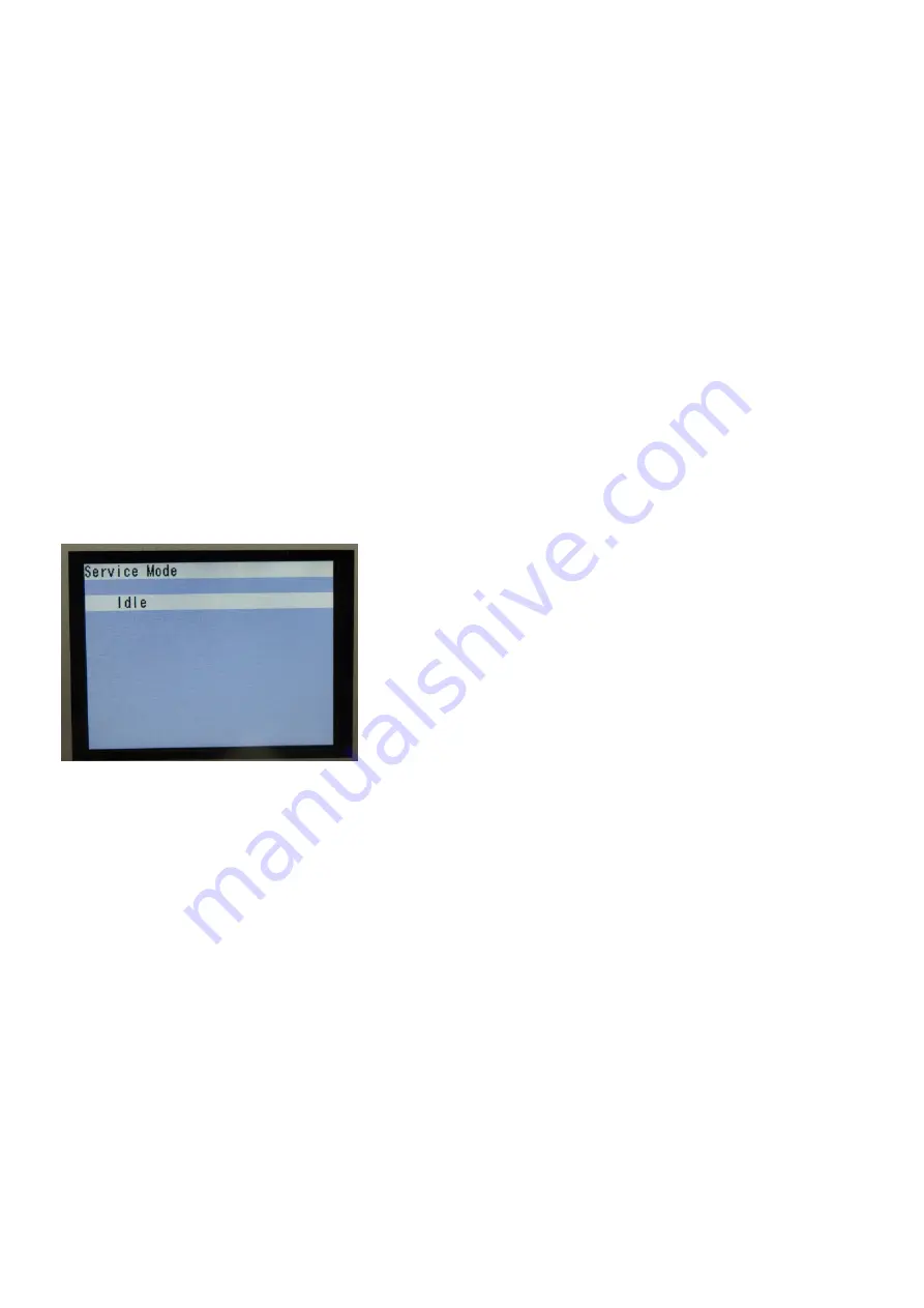
iv. When the Power LED lights in green and the machine displays "Service Mode Idle," the machine is ready for the
service mode operation.
LCD ready for the service mode operation:
2) Start the Service Tool on the connected computer.
i. When a button is clicked in the Service Tool dialog box, that function is performed. During operation of the selected
function, all the Service Tool buttons are dimmed and inactive.
ii. When the operation is completed, "A function was finished." is displayed, and another function can be selected.
iii. If a non-supported function is selected, "Error!" is displayed. Click
OK
in the error message dialog box to exit the
error.
46 / 64
Summary of Contents for PIXMA MX860 series
Page 8: ...5 64 ...
Page 30: ...6 Separate the scanner from the document feeder no screws 27 64 ...
Page 32: ...29 64 ...
Page 34: ...2 Remove the document feed cover eject tray and tray base 4 screws 31 64 ...
Page 36: ...4 Remove the LCD ass y no screws 5 Remove the panel board 10 screws 33 64 ...
Page 40: ...7 Remove the PE sensor board 5 screws 37 64 ...
Page 50: ... 2 Service Tool functions Service Tool screen Version 1 030 47 64 ...
Page 58: ...PTT parameter print sample for the MX860 Japan model 4 3 PTT Parameter Mode 55 64 ...
Page 65: ... 2 Service test print Service test print sample 62 64 ...
Page 66: ... 3 Ink absorber counter value print Print sample 4 6 Verification Items 63 64 ...
Page 74: ...REFERENCE PRINTER UNIT FIGURE 13 OPTION CONSUMABLES FIGURE 14 TOOL A 3 ...
Page 75: ...B PARTS LAYOUT PARTS LIST FIGURE 1 PACKING CONTENTS PRINT HEAD B 1 ...
Page 77: ...FIGURE 2 AC ADAPTER B 3 ...
Page 79: ...FIGURE 3 EXTERNAL COVERS SCANNER UNIT B 5 ...
Page 81: ...FIGURE 4 DOCUMENT PRESSURE PLATE UNIT B 7 ...
Page 83: ...FIGURE 5 OPERATION PANEL UNIT B 9 ...
Page 85: ...FIGURE 6 MAIN CASE UNIT FRONT DOOR UNIT B 11 ...
Page 87: ...FIGURE 7 BOTTOM CASE INK ABSORBER B 13 ...
Page 89: ...FIGURE 8 LOGIC BOARD ASS Y PE SENSOR BOARD ASS Y B 15 ...
Page 91: ...FIGURE 9 SHEET FEED UNIT B 17 ...
Page 93: ...FIGURE 10 CARRIAGE UNIT PRESSURE ROLLER UNIT B 19 ...
Page 95: ...FIGURE 11 PLATEN UNIT SPUR UNIT B 21 ...
Page 97: ...FIGURE 12 PURGE DRIVE SYSTEM UNIT SWITCH SYSTEM UNIT B 23 ...
Page 99: ...REFERENCE PRINTER UNIT B 25 ...
Page 100: ...C OPTION CONSUMABLES FIGURE 13 OPTION CONSUMABLES C 1 ...
Page 103: ...E TOOL FIGURE 14 TOOL E 1 ...


