background image

4 - 47

CHAPTER 4

C . O t h e r s

Printer

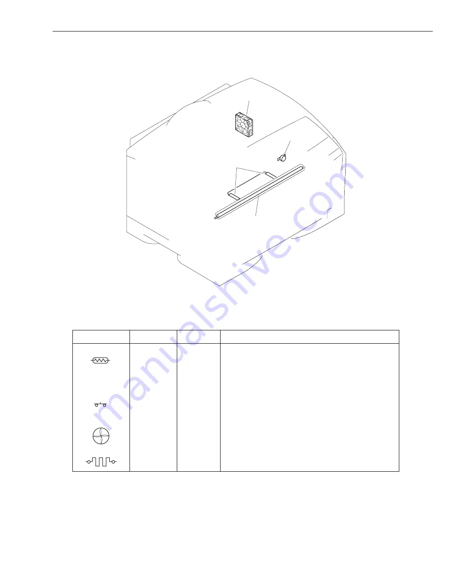
TH101

THSW101

H101

FM101

Figure 4-9-3

Table 4-9-3

S y m b o l

N a m e

T h e r m i s t o r

T h e r m i s t o r

T h e r m a l
s w i t c h

Fan motor

H e a t e r

N o t a t i o n

T H 1 0 1

T H 1 0 1

T H S W 1 0 1

F M 1 0 1

H 1 0 1

D e s c r i p t i o n

Main thermistor (for detection of temperature at middle
of fixing assembly surface)

Sub thermistor (for detection of temperature at edges
of fixing assembly surface)

Thermal switch (for detection of error temperature of
the fixing roller)

Heat discharge fan

Fixing heater

Summary of Contents for LBP-2000

Page 1: ...REVISION 0 FY8 13HQ 000 COPYRIGHT 2001 CONON INC CANONLBP 2000REV 0AUG 2001 AUG 2001 SERVICE MANUAL ...

Page 2: ...Use of this manual should be strictly supervised to avoid disclosure of confi dential information COPYRIGHT 2001 CANON INC ...

Page 3: ...in the mechanical electrical systems of the Printer according to function as well as timing at which associated mechanisms operate Chapter 3 Mechanical System shows the mechanical construction of the Printer and how to disassemble assemble and adjust its components Chapter 4 Troubleshooting indicates how to correct various faults and make checks adjust ments and provides standards to follow APPEND...

Page 4: ...n Sequence 2 6 II ENGINE CONTROL SYSTEM 2 7 A Outline of the Electrical Circuitry 2 7 B Inputs to and Outputs from the DC Controller 2 9 C Controlling the Fixing Mechanisms 2 1 2 D High Voltage Power Supply Circuit 2 1 8 E Low Voltage Power Supply Circuit 2 2 3 F Video Interface Control 2 2 5 G Other Control 2 2 7 III LASER SCANNER SYSTEM 2 3 0 A Outline 2 3 0 B Laser Control Circuit 2 3 1 C Scann...

Page 5: ...ing Flow Chart 4 1 B Making Initial Checks 4 4 C Test Print 4 5 II TROUBLESHOOTING IMAGE FAULTS 4 1 0 III MEASURES AGAINST JAMS 4 1 7 IV FEEDING FAULTS 4 2 1 V MALFUNCTIONS 4 2 3 VI CORRECTING A FAULT STATUS CONDITION 4 2 5 VII STANDARDS AND ADJUSTMENTS 4 3 1 A Making Mechanical Adjustments 4 3 1 B Making Electrical Adjustments 4 3 2 C Copying the Counter Readings 4 3 3 D Variable Resistors VR Lig...

Page 6: ...CT OUTLINE I FEATURES 1 1 II SPECIFICATIONS 1 2 III SAFETY 1 5 IV NAMES OF PARTS 1 6 V INSTALLATION 1 9 VI RELOCATING THE PRINTER 1 2 1 VII ROUTINE MAINTENANCE INSPECTION BY THE USER 1 2 2 VIII USING THE PRINTER 1 2 5 ...

Page 7: ...sleep mode power saving mode after remaining in standby mode for a specific period of time thereupon automatically cutting the power to the fixing heater and ultimately limiting the total consumption of power The printer is also able to print in toner save mode in which it prints using less toner lighter output to save on toner 5 Auto interface switching mechanism In addition to the parallel inter...

Page 8: ... Cassette Paper feeder option Paper type Plain paper thick paper colored paper label sheet recycled paper transparency film envelopes Paper size Multifeeder tray Plain paper 64 g m2 to 90 g m2 recommended or thick paper 91 g m2 to 157 g m2 recommended or label sheets of following dimen sions 76 2 W x 98 L to 297 W x 431 8 L mm Cassette Plain paper 64 g m2 to 90 g m2 recommended of following sizes ...

Page 9: ...arrives form the video controller to when a single A4 sheet is received and deliv ered to the delivery tray May be longer depending on the type of paper and the fixing mode selected 3 At 20ºC room temperature without an expansion RAM The above specifications are subject to change for product improvements 2 Video Controller 1 CPU Power PC 405 200 MHz 2 Memory RAM 8 MB built in may be expanded to 72...

Page 10: ...Server The above specifications are subject to change for product improvements 2 Paper feeder 1 Pickup paper size A3 B4 A4 A4R vertical B5 A5 11 x 17 LGL LTR Executive plain paper 64 g m2 to 90 g m2 recommended 2 Cassette size 25 mm deep about 250 sheets of 64 g m2 paper 3 Cassette type Universal may be configured for following A3 B4 A4 A4R verti cal B5 A5 11 x 17 LGL LTR Executive 4 Dimensions 48...

Page 11: ...d small amounts of colorings If your skin or clothes came into contact with toner remove as much of it as possible using dry tissues then rinse with cold water Do not use warm water The toner will turn into jelly and will not come off Do not bring toner into contact with vinyl material They tend to react with each other C Safety of Ozone The Printer s charging roller generates a minute amount of o...

Page 12: ...ery tray 2 Front cover 3 Open close lever 4 Multifeeder tray 5 Paper guide 6 Cassette 7 Power supply switch 8 Control panel 1 Expansion board slot cover 2 Expansion board slot 1 3 Expansion board slot 2 4 Power receptacle 5 Test Print switch 6 Test Print switch 7 Leading edge margin adjusting volume VR101 8 USB interface connector 9 Parallel interface connector 10 Slot cover ...

Page 13: ...ehind the front cover 4 3 1 2 Figure 1 4 3 1 Static eliminating brush 2 Transfer charging roller 3 Toner cartridge guide 4 Registration roller 2 Paper feeder 2 3 1 Figure 1 4 4 1 Connector 2 Positioning pin 3 Cassette ...

Page 14: ...Delivery roller 7 Fixing heater 8 Control panel 9 Laser scanner unit 10 Cassette 11 Cartridge 12 Primary charging roller 13 Photosensitive drum 14 Developing cylinder 15 Cassette pickup roller 16 Cassette separation pad 17 Manual feed separation pad 18 Manual feed pickup roller 19 Multifeeder tray 2 Paper feeder 1 2 3 4 Figure 1 4 6 1 Feeding roller 2 Cassette pickup roller 3 Cassette separation p...

Page 15: ...he following requirements if possible visit the site of installa tion before the Printer is delivered 1 Power supply The power supply must satisfy the following AC 10 of ratings Frequency 50 60 2 Hz 2 Operating environment The site must satisfy the following Its floor must be level Its temperature and humidity are as follows Ambient temperature 7 5ºC to 32 5ºC 45 5 to 90 5ºF Ambient humidity 5 to ...

Page 16: ...o accommodate the Printer s feet rubber pads and strong enough to withstand the Printer s weight 338 440 325 mm 434 249 1300 123 mm 488 100 106 312 620 720 mm 260 277 90 67 90 84 436 408 51 31 16 36 mm Dimensions Around the Printer standard Locations of the Feet View form the side with 3 paper feeders View from the Side standard Each rubber foot is 5 mm in height and its tip is a square of 18 x 18...

Page 17: ... the position pins on the paper feeder fit into the openings in the Printer s bottom 6 Remove the tape used to keep the parts in place 7 Open the multifeeder tray and pull the open close lever to the front to slide out the front cover 8 Remove the protective tape used to keep the transfer charging roller in place 9 Lock the open close lever and close the front cover and the multifeeder tray 10 Sli...

Page 18: ...Bs by static charges 1 Turn off the Printer and disconnect the power cord and the interface cable 2 Take out the hard disk from its packaging box 3 Remove the vinyl bag used to cover the hard disk 4 Remove the screw 1 and detach the expansion board slot cover 2 2 1 Figure 1 5 2 5 Remove the screw 3 and detach the expansion board slot 1 cover 4 3 4 Figure 1 5 3 ...

Page 19: ...n the hard disk along the guide rail 5 Figure 1 5 4 7 Secure the top and bottom of the hard disk with the 2 screws 6 that come with the hard disk 6 Figure 1 5 5 8 Attach the expansion board slot cover and the power cord 9 Connect the Printer s power cord to the power outlet ...

Page 20: ...echanisms when you install the built in print server to the Printer Take particular care not to touch the parts in electric circuits 1 Unpack the print server 2 Take out the print sever from its packaging box 3 Remove the vinyl bag used to cover the print server 4 Remove the screw 1 and detach the expansion board slot cover 2 2 1 Figure 1 5 6 5 Remove the screw 3 and detach the expansion board slo...

Page 21: ...1 5 8 7 Secure the top and bottom of the print server using the two screws 6 that come with the print server 6 Figure 1 5 9 8 Connect the network cable to the connector of the print server to suit the network environ ment Figure 1 5 10 9 Connect the power cord 10 Connect the Printer s power cord to the power outlet ...

Page 22: ... Figure 1 5 12 5 Checking the operation 1 Put paper in the cassette 2 Connect the grounding wire to the Printer 3 Connect the power cord to the Printer and the power outlet and turn on the power switch Be sure that the power cord is one designed for the Printer 4 When the Printer is in standby state press the Go key so that it enters off line state 5 Press the Menu key once and press the Item key ...

Page 23: ...installing or removing the following flash memory option Adobe PostScript Level 3 Module option expansion RAM DIMM op tion hard disk option built in print server option 4 Be sure to use a shielded cable when connecting the Printer s parallel interface connector and an external device Moreover make sure that the parallel interface cable is no longer than 3 m 5 Be sure to use a twisted pair LAN cabl...

Page 24: ...ts the requirements in Table 1 5 1 in addition 1 Avoid direct rays of the sun 2 Avoid a place subject to vibration 3 Avoid shocks as by hitting or dropping it Table 1 5 1 Temperature Humidity Requirements for Storage Normal 9 10 of total storage period Temperature Humidity Severe 1 10 of total storage period Total storage period Atmospheric pressure Change in temperature within about 3 min 2 5 yr ...

Page 25: ...ion For the user the period is indicated on the package and the packing boxes year month 2 5 years after the date of manufacture The use of a cartridge after the date indicated may not bring about expected print quality making it desirable to use it up before the date indicated c Points to note when handling 1 When fitting a new cartridge or if some areas of the output image show white spots becau...

Page 26: ...ver Be sure it is laid with the label surface facing upward 7 Do not disassemble the cartridge Reference If the photosensitive drum is exposed to light of 1500 lux general lighting for 5 min and then left alone in the dark for 5 min the faults can be corrected to a level satis factory to practical uses It is nevertheless important to avoid direct rays of the sun which is about 10000 to 30000 lux i...

Page 27: ...rting to move the Printer If shipping tape is used be sure to attach it so that the tape protection is over the gears and the bushings thus protecting the gears and the bushings of the transfer charging roller from adhesive If common tape is to be used be sure to put a protective material e g lint free paper between the tape and the gears bushings thus protecting the gears and the bushings of the ...

Page 28: ... IV A 1 2 Replacing the Cassette Pickup Roller and Replacing the Cassette Separation Pad 3 Fixing roller If the back or face of printed sheets have black dots clean the fixing roller as follows 1 Prepare an A4 or LTR sheet of paper for printing 2 Press the Go key so that the Printer enters off line state 3 Press the Menu key until the status indicator panel indicates TEST MENU 4 Press the Item key...

Page 29: ...he pickup roller if faults still occur after cleaning the manual feed pickup roller and the manual feed separation pad must be replaced at the same time about 50 000 pages 1 Obtain a manual feed tray cleaning tool and a cleaning sponge Cleaning sponge Manual feed tray cleaning tool Figure 1 7 3 2 Peel the sticker from the cleaning sponge and attach it as shown to the manual feed cleaning tool Figu...

Page 30: ...u key until the status indicator panel indicates TEST MENU 7 Press the Item key until the status indicator panel indicates CLEANING ROLLER Then press the Enter key so that the Printer starts to clean the roller Note 1 Check to make sure that no paper exists in the multifeeder tray before executing CLEAN ING ROLLER Otherwise the paper will be picked up causing a jam 2 Be sure to detach the cleaning...

Page 31: ...isk access indicator Blinking The hard disk is being accessed OFF The hard disk is not being accessed 3 Alarm indicator ON An error has occurred and printing has stopped OFF Operation in normal and there is no error 4 Menu key With the printer off line press the Menu key to scroll through the menu names and return to the first menu name To scroll back through the menu names in the opposite directi...

Page 32: ...n the key name on the operation panel 9 Go Takes the printer off line and back on line When the On Line indicator is on the printer is ready to receive data and print When the On Line indicator is off the printer is off line and the other keys on the operation panel can be used to view and change settings Resumes printing after the printer display a message and stops printing For most situa tions ...

Page 33: ...e Go key to set the printer off line The On Line indicator goes OFF and PAUSED is displayed in the top line 3 Press the Menu key to display the name of the first menu Press the Menu key until you see the m e n u 4 Press the Item key to display the name of the first item on the menu Press the Item key until you see the item 5 Press the Value key until you display the values you want to change 6 If ...

Page 34: ...JAM LOG Clears the jam log 5 Shut down This menu is used to shut down the printer You should always use this menu to shut down the printer if the optional Hard Disk HD 65 has been installed C Service Menu The Service Menu is a hidden menu and contains the following sub menus 1 ERR JAM LOG MENU Print of Error Jam log Report 2 FORMAT MENU Format of Hard disk drive and Flash ROM 3 NVRAM MENU Display ...

Page 35: ...BS NO AUTO CLEAR LOG PER 55 JOBS NO YES YES RESET MENU JOB LOG MENU YES AUTO PRINT LOG PER 30 JOBS NO YES AUTO CLEAR LOG PER 30 JOBS NO JOB LOG FULL STOP WARNING DAYLIGHT SAVING OFF GMT DIFFERENTIAL TIME 00 0 ON 12 0 to 12 0 by 0 5 RESET MENU RESET MENU FONTS FORMS STORED JOB JOB LOG ERROR LOG JAM LOG LANGUAGE MENU LANGUAGE MENU LANG ENGLISH DANISH DUTCH FINNISH FRENCH GERMAN ITALIAN NORWEGIAN POR...

Page 36: ...CHAPTER 1 1 30 ...

Page 37: ...M MENU NVRAM MENU NVRAM CHECK DUPLICATE Press ENTER NVRAM CHECK is done i After NVRAM CHECK is done panel display goes back to NVRAM MENU above ii After NVRAM COPY is done The system is rebooted if required then goes to READY In details See VII C Copying the Counter Readings in Chapter 4 section ERR JAM LOG MENU ERR JAM LOG MENU PRINT ERROR LOG JAM LOG FORMAT MENU FORMAT FLASH IGNORE FLASH SHIFT V...

Page 38: ...CHAPTER 1 1 32 ...

Page 39: ...H or without a slash the signal is true generated in the presence of a supply voltage level it is false not generated in the absence of a voltage i e GND level The opposite is true of a signal shown as being L or preceded by a slash The Printer uses a microprocessor but its mechanisms are omitted from discussions as they cannot be checked in the field In addition PCBs are not to be repaired in the...

Page 40: ...Image formation system Multifeeder tray Transfer charging roller Primary charging roller Laser exposure system Laser driver PCB Laser scanner assembly Photosensitive drum To external device e g host computer Engine control system DC controller PCB Cassette Low voltage power supply Cassette Cassette pickup assembly Paper feeder option Paper feeder option Paper feeder option Cassette Cassette pickup...

Page 41: ...perature of the fixing assembly is 145 C or higher From when the power switch is turned on to when the surface temperature of the fixing roller reaches 140 C From when warm up ends to when the main motor is turned on and then off From when the warm up interval ends to when the PRNT signal arrives from the video controller Or from when LSTR ends to when the PRNT signal arrives from the video contro...

Page 42: ... assembly is 150 C or higher 27 sec or more passes after the start of supplying the fixing assembly with power and in addition the temperature of the fixing assembly is 145 C or higher WMUP WMUPR WAIT STBY Primary high voltage DC Main motor M101 Registration clutch CL102 Developing bias AC Transfer high voltage Fixing heater H101 Developing bias DC Primary high voltage AC 1 0 0 56 approx 0 46 appr...

Page 43: ... the transfer charging roller INTR initial rotation From when the PRNT signal arrives from the video controller to when the DC controller generates the TOP signal From when the warm up rotation interval ends to when the PRNT signal arrives from the video controller Or from when LSTR ends to when the PRNT signal arrives from the video controller or when the power switch is turned off Interval To co...

Page 44: ...101 Registration clutch CL102 Delivery sensor PI103 Primary charging AC Primary charging DC Main motor M101 Developing bias DC PRNT Developing bias AC Laser diode Transfer high voltage Fixing heater H101 STBY INTR PRINT LSTR TOP signal STBY 0 15 0 5 0 06 may be adjusted 0 03 0 07 Negative bias unit sec 4 5 approx 0 46 0 76 0 46 1 03 approx 0 17 approx 0 1 Figure 2 1 3 ...

Page 45: ...FF Fixing assembly temperature 140 C Is fixing assembly temperature 195 C target within 25 sec from fixing heater ON Auto delivery will be initiated if the registration paper sensor detects paper A jam will be identified if the registration paper sensor or the delivery sensor detects paper The Printer changes to standby status for the following conditions after the power switch is turned on to red...

Page 46: ...data from an external device The following is a block diagram for the cir cuitry Fixing assembly High voltage power supply circuit Cartridge Low voltage power supply circuit DC controller PCB 5V AC input Laser driver Video controller Scanner motor BD circuit Clutch Solenoid Paper feeder option Reset IC 24V Power supply assembly Heat discharging fan Main motor Heater control circuit 3 3V Sensor Sen...

Page 47: ...ng with the paper feeder b ASIC 1 controlling the communication with the video controller PCB 2 controlling the high voltage power supply circuit 3 controlling the laser scanner 4 controlling the fixing heater 5 controlling the multifeeder paper sensor paper size detecting switch c Reset IC The reset IC monitors the 3 3V voltage and resets the CPU in a specific time if the power supply voltage rea...

Page 48: ...aper sensor PI104 Paper size detecting switch J110 1 2 4 5 3 J902 5 4 2 1 3 PSSN4 PSSN3 PSSN2 PSSN1 See V B Detecting Paper Size in Chapter 2 Main thermistor When the temperature of the fixing roller increases the voltage decreases analog signal When the temperature of the fixing roller increases the voltage decreases analog signal When 24 V is supplied H Test print switch When L engine test print...

Page 49: ... J106 16 17 CL102 Main motor Scanner motor J106 8 9 12 13 10 11 M101 J106 4 5 6 7 J109 3 1 2 M102 MTRONO MLOCK ACCO DCCO 24V 24V 24V For details see II G Other Control in Chapter 2 For details see III C Scanner System in Chapter 2 For details see II G Other Control in Chapter 2 J906 2 1 1 2 J903 6 5 4 3 2 1 J904 2 1 1 2 FANDRV FANLOCK Heat discharging fan FM101 J905 2 1 1 2 When H CL102 goes ON RG...

Page 50: ...r option AC power input For details see II F Controlling the Video Interface in Chapter 2 BD input signal pulse signal J102 1 2 3 4 6 7 5 8 J907 8 7 6 5 3 2 4 1 5V 3 3V BDIN DPICH ENBLO LONO VDO VDO Laser unit Laser scanner assembly J102 9 10 11 J908 3 2 1 BD detection PCB Video controller PCB Options controller PCB When L turns on the laser to suit the VDO signal and the VDO signal When L turns o...

Page 51: ...eck the right edge of the fixing roller When the surface temperature increases the resistance of TH101 will decrease causing the voltage of the main thermistor TH1 and the sub thermistor signal TH2 to decrease The DC controller PCB controls the fixing heater drive signal FSRDRV based on the voltage level of the TH1 signal and the TH2 signal thereby controlling the surface temperature of the fixing...

Page 52: ... the distance between sheets is increased In continuous printing the distance between sheets is increased Remarks Mode Note Normal mode is used when printing on plain paper default Rough paper mode is used when printing on heavy paper or in a low temperature environment Transparency mode is used when printing on transparencies Normal L mode is used to prevent curling on plain paper L b Control whe...

Page 53: ...ched and the target temperature is lowered in steps over time while continuous printing takes place thereby using the control temperature specific to each mode If the PRNT signal is absent temperature control will be as in normal mode regardless of the selected mode c Controlling in sleep mode power saving mode The fixing heater H101 remains OFF while the Printer is in sleep state The target tempe...

Page 54: ...nd on the power supply PCB to cut the AC power to the fixing heater H101 Relay circuit Fixing assembly P1 CB NF NF ASIC CPU Zero cross circuit Heater drive circuit J1201 5 J105 31 RLYDRV FSRDRV 4 32 HEATDT 1 35 J1201 3 J105 33 ZEROXI Power supply PCB DC controller PCB AC DC F1 SW1 H101 THSW101 J103 6 GND GND TH2 5 4 GND TH1 3 2 THCNCT 1 1 3 1 3 J915 3 3V 5V 24V Low voltage power supply PCB RL1 Hea...

Page 55: ... disconnection detection circuit found on the DC controller PCB monitors the THCNCT signal if the THCNCT signal goes Low the CPU will identify the condition as indicating disconnec tion of the thermistor connector c Thermistor cutting the power for overheating If the internal temperature of the thermal switch THSW101 exceeds about 230 C thermal switch will go OFF thereby cutting the power to the f...

Page 56: ... 80 C within 10 sec after it has exceeded 60 C the main thermistor reading does not reach 100 C within 10 sec after it has exceeded 80 C the main thermistor reading does not reach 120 C within 10 sec after it has exceeded 100 C the main thermistor reading does not reach 140 C within 10 sec after it has exceeded 120 C the main thermistor reading does not reach 160 C within 10 sec after it has excee...

Page 57: ... voltage power supply circuit is mounted on the DC controller PCB and is used to apply a voltage generated by combining DC and AC voltages to the primary charging roller and the developing cylinder in response to commands from the CPU and according to the print signal PRNT from the video controller PCB it applies a positive or negative DC voltage to the transfer charging roller It also varies the ...

Page 58: ... Transfer bias Main switch ON 140 C unit sec 0 46 approx Negative bias Figure 2 2 8 During printing A4 2 pages continuous PRINT STBY 4 7 approx 0 46 0 1 0 76 Print start command PRNT Main motor M101 Scanner ready signal SCNRDY Primary AC bias Primary DC bias Developing AC bias Developing DC bias Transfer bias LSTR PRINT INTR STBY unit sec Negative bias Sheet to sheet bias 2 0 approx 0 17 approx 0 ...

Page 59: ...g DC bias output level signal DCPWM it also applies a voltage which is a combination of a primary AC bias and a primary DC bias to the primary charging roller The primary AC bias is detected by the primary AC bias current detection circuit and is fed back to the AC generation circuit by way of the comparison circuit thereby controlling the current of the primary charging bias The primary DC bias i...

Page 60: ...nd primary developing DC bias output level signal DCPWM and applies a voltage which is a combination of a developing AC bias and a developing DC bias to the developing cylinder When not forming images the developing DC bias output switch signal DVDCUP is used to apply the developing DC bias with a voltage higher than that used when forming an image to prevent soiling of the pressure roller The dev...

Page 61: ... If retry operation is executed three times as the result of toner level detection at power on about 40 sec of wait time will be required 2 As many as about 100 pages may be printed after the message READY TONER LOW is indicated i e about 60 g of toner remains d Transfer T403 Tr TRCRNT TRPWM To transfer charging roller DC controller PCB Transfer bias circuit ASIC CPU Positive current detection cir...

Page 62: ... Motor Heat discharging fan Right door switch Solenoid Laser unit BD detection PCB Paper feeder Clutch J1201 8 15 J1201 18 19 J1201 22 27 Power supply PCB DC controller PCB Control panel 5V 3 3V Video controller PCB 5V 5V 3 3V 3 3V Paper size sensor 3 3V Left door switch 24VR 24V 24V 24VR 24VR 5V 24V 5V 24V 5V Paper feeder Paper feeder 24V 5V AC DC Option F1 F4 F5 F3 24VR SW1 Figure 2 2 13 ...

Page 63: ... caused by a short circuit or the like in any of the loads If the output power is cut turn off the power switch disconnect the power plug remove the cause of activation and leave the Printer alone for about 3 min or more before turning on the power once again thereby resetting the protective circuit The power supply PCB is also equipped with four fuses which will blow if overcurrent flows into the...

Page 64: ...ircuit and the video controller circuit and provides an outline of operation sequence executed using these interface signals a System block diagram Video controller PCB Video interface signal Figure 2 2 15 External device e g host computer Printer DC controller PCB D input signal BDIN Video signal VDO VDO Laser unit BD PCB Figure 2 2 14 ...

Page 65: ...sends the vertical sync request signal TOP to the video controller In response to the horizontal sync signal BDO from the DC controller the video controller sends video signals VDO VDO synchronized with the BDO signal and the TOP signal to the laser driver by the DC controller These video signals VDO VDO are sent to the laser driver as two low voltage differential signals The laser driver uses the...

Page 66: ...to rotate the main motor When the main motor starts to rotate and reaches a specific revolution it causes the main motor rotation detection signal MLOK to go Low The CPU will identify a fault in the main motor under any of the following conditions commu nicating to the video controller and indicating E011 on the LCD of the control panel 1 At the start of warm up rotation WMUPR the MLOK signal does...

Page 67: ... such times as indicated J109 3 2 1 24V 24V 3 3V 24V Heat discharging fan FM101 FANDRV FANLOCK FANON FANFULL ASIC CPU DC controller PCB figure 2 2 17 A4 2 Pages Continuous WAIT STBY INTR half speed 16 V full speed 24 V PRINT PRINT LSTR 30 sec STBY Heat discharging fan FM101 Registration paper sensor PI101 Delivery sensor PI103 Power switch ON sleep OFF PRNT signal IN Power switch OFF sleep ON Figu...

Page 68: ...ter causes the fan full speed rotation signal FANFULL to go Low and supplies the fan drive voltage FANDRV about 16 V to rotate the discharging fan at half speed The CPU monitors the fan lock detection signal FANLOCK at all times while the heat dis charging fan is rotating if the FANLOCK signal is Low for a specific period of time or longer the CPU will identify the condition as indicating a fault ...

Page 69: ...the laser diode according to the video signals VDO VDO to generate a modulated laser beam The modulated laser beam is turned into a parallel beam by the work of the collimator lens and the cylindrical lens and is directed to the 6 faceted mirror which is rotating at a specific speed The laser beam reflected by the 6 faceted mirror is guided to the imaging lens and the reflecting mirror mounted in ...

Page 70: ...sponse to the video signals VDO VDO from the video controller to turn on off the laser diode LD at a specific intensity The VDO and VDO signals from the video controller are low amplification differential signals with suppressed radiating noise and they are sent to the receiver in the laser unit as they are The receiver serves to demodulate the low voltage differential signals and to forward them ...

Page 71: ...s an APC method in which its laser driver detects and controls for each dot the intensity of light at all times as long a the laser diode remains ON 3 Controlling the horizontal synchronization The ASIC generates the un blanking signal inside it using the BD input signal BDIN coming from the BD PCB mounted to the laser scanner assembly The ASIC causes the laser forced emission signal LONO to go L ...

Page 72: ...ge erase TOPE and left right image mask signal MSK TOPE and MSK are used within the ASIC and are not sent outside it To prevent writing by the laser beam outside the non image area except during the un blanking period it causes the image formation enable signal ENBLO to go L while the TOPE signal and the MSK signal remain L The laser driver turns on the laser diode when the ENBLO signal is L and i...

Page 73: ...he video controller it causes the scanner motor acceleration signal ACCO to go L in 0 15 sec When the ACCO signal goes L the scanner driver IC rotates the scanner motor and increases the speed of its rotation while the ACCO signal remains L While the scanner motor is rotating the ASIC forces the laser ON causing the BD PCB to send the BDIN signal The ASIC compares the cycle of the BDIN signal and ...

Page 74: ...laser is tuned on when the scanner motor is started up 3 The rotation of the scanner motor fails to reach 97 of the target rotation 7 sec after the scanner is started up 4 The speed of the scanner motor is higher than the target speed for at any print within 20 sec after the motor is slowed down as found to be too fast at time of start up 5 The cycle of the BIDN signal deviates more than 2 for a c...

Page 75: ... of the image leading edge The following diagrams show the timing of operation used for delivery A4 horizontal the timing however varies depending on the timing of previous delivery and the printer settings Scanner pre rotation Start of print 4 3 sec approx 9 1 sec approx 12 6 sec approx End of delivery Start of print Scanner Pre Rotation ON PRNT PRNT End of delivery Scanner Pre Rotation OFF Figur...

Page 76: ...e is then turned into a visible image on the developing cylinder using toner the resulting visible image is then transferred to paper by the transfer charging roller The surface of the photosensitive drum is cleaned by the cleaning blade which removes re sidual toner it is then charged to a uniform potential by the primary charging roller to be ready for a new image The cartridge of the Printer is...

Page 77: ...eloping cylinder Cartridge Blade Primary charging roller Photosensitive drum Cleaning blade Laser beam Figure 2 4 2 The Printer uses a 2 layer seamless drum the outer coating is a photo conducting laser made of optical photoconduction OPC material while the inner coating is an aluminum substrate Photo conducting layer Substrate Figure 2 4 3 ...

Page 78: ...Step 4 transfer Step 5 separation grounding 4 Fixing Block Step 6 fixing 5 Drum Cleaning Block Step 7 drum cleaning 7 drum cleaning 1 primary charging 2 laser beam exposure 3 development 4 transfer 5 separation Cassette Multifeeder Registration 6 fixing delivery 3 Transfer Block 4 Fixing Block 2 Development Block 5 Drum Cleaning Block 1 Latent static Image Formation Block rotation of photosensitiv...

Page 79: ...ea Dark area Laser beam exposure step 2 Transfer step 4 Primary charging step 1 Primary charging step 1 Surface potential V Figure 2 4 5 Step 1 primary charging Photosensitive drum Primary charging roller AC bias DC bias Figure 2 4 6 To prepare for the formation of a latent image the surface of the photosensitive drum is charged to a uniform negative potential The Printer uses a method of primary ...

Page 80: ...m thus turning it into a visible image The Printer uses a toner projection development method and its toner is a 1 component type Step 3 development Photosensitive drum Developing cylinder Blade Stirring rods AC bias DC bias Figure 2 4 8 Note The light area of the surface of the photosensitive drum actually carries a negative poten tial but the diagram expresses it as carrying a positive potential...

Page 81: ...cylinder will cause the toner to jump to and stick to the surface of the photosensitive drum This is referred to as toner projection and is used to turn the latent static image on the surface of the photosensitive drum into a visible image Voltage V Surface potential of developing cylinder Surface potential of drum light area Surface potential of drum dark area V V 0 Time t DC bias Figure 2 4 9 To...

Page 82: ...drum A roller transfer method is used which allows smooth movement of paper and reduction of generated ozone Step 5 separation Paper Transfer charging roller Photosensitive drum Static eliminating brush Ground Figure 2 4 11 The rigidity of paper is used to separate paper from the photosensitive drum The static eliminating brush is used to prevent the toner image from flying astray in dots when pap...

Page 83: ...er are thus subjected to pressure and heat thereby fusing the toner with the fibers of the paper and ultimately making the image permanent Step 6 fixing Toner Paper Fixing roller Fixing heater Separation claw Static eliminating brushes Pressure roller Figure 2 4 12 The surface of the fixing roller is coated with fluorine and the static brush is grounded to prevent offset The separation claws are u...

Page 84: ...rface of the photosensitive drum thereby ensur ing the reproduction of sharp images for the next run Photosensitive drum Scoop up sheet Cleaning blade Cleaner case Figure 2 4 13 In preparation for the next run the cleaning blade is used to scrape off the toner remaining on the surface of the photosensitive drum for cleaning The scraped toner is then collected inside the cleaner case of the cartrid...

Page 85: ...oller it is stopped and is made to arch on its leading edge thus ridding itself of any skew Thereafter the registration clutch CL102 goes on to move the paper farther A specific period of time after the registration paper sensor PI101 goes on as set by the leading edge registration adjusting volume VR101 on the DC controller the vertical sync signal TOP is sent by the DC controller to the video co...

Page 86: ...detection signal Multifeeder paper detection signal MPSNS Delivery paper detection signal POSISNS Registration paper detection signal RGSNS Cassette paper detection signal Separation pad Photosensitive drum Transfer charging roller manual feed pickup roller Registration roller Figure 2 5 1 PI101 registration paper sensors PI102 multifeeder paper sensor PI103 delivery sensor PI104 cassette paper se...

Page 87: ... CL102 SL101 Multifeeder pickup solenoid drive signal MPFDO Registration clutch drive signal RGON Cassette pickup clutch drive signal CSTFD DC controller PCB Figure 2 5 2 SL101 multifeeder pickup solenoid CL101 multifeeder pickup clutch CL102 registration clutch M101 main motor ...

Page 88: ...rent from the length selected by the video controller for the paper placed in the multifeeder tray by 10 mm the CPU will identify a size mismatch condition and communicate the fact to the video controller 2 Detecting the size of the paper in the multifeeder tray As in the case of the cassette the multifeeder tray uses the registration paper sensor PI101 to find out the size of paper However a mism...

Page 89: ... CL101 is turned off as soon as the paper arches to stop the rotation of the cassette pickup roller At the same time the registration clutch CL102 is turned on to move the paper once again for the transfer separation and fixing blocks Paper Path for Cassette Pickup Figure 2 5 3 Basic Sequence of Operation for Cassette Pickup Main motor M101 Registration clutch CL102 Pickup clutch CL101 Registratio...

Page 90: ...to move up to put the paper in contact with the multifeeder pickup roller At the same time the manual feed pickup roller makes a single rotation thus feeding a single sheet of paper from the multifeeder The paper then moves past the registration paper sensor PI101 and reaches the registration roller At this time the registration roller is not rotating and the paper stops to arch along its leading ...

Page 91: ...ontrol The Printer executes pickup retry control if paper fails to reach the registration paper sensor PI101 in about 0 88 sec after the multifeeder pickup solenoid SL101 goes on because of wear on the roller or a pickup fault The multifeeder pickup solenoid SL101 goes on pick up retry control for a second time The retry sequence is as follows Main motor M101 Multifeeder pickup solenoid SL101 Regi...

Page 92: ...ted from the photosensitive drum is moved to the inside of the fixing assem bly and the toner is fused to its fibers by the work of the fixing roller the paper is then moved outside the fixing assembly The paper is detected by the delivery sensor PI103 and is then delivered face down DC controller PCB PI103 Delivery detection signal POSISNS M101 Figure 2 5 9 ...

Page 93: ... identified if the registration paper sensor PI101 does not detect the leading edge of paper within a specific period of time after the start of pickup Inside the cassette the cassette pickup roller remains in contact with the paper at all times for this reason pickup retry control will not be executed but a longer jam detection margin is used When the multifeeder tray is used as the source of pap...

Page 94: ...signal IN Jam message ON Normal Error 2nd sheet picked up Figure 2 5 11 Sequence for a Pickup Delay Jam multifeeder tray Main motor M101 Multifeeder pickup solenoid SL101 Registration paper sensor jam check Registration paper sensor PI101 Standby Pickup control PRNT signal IN Pickup retry operation 1 started Pickup retry operation 2 started Jam message ON Error Error Error Figure 2 5 12 ...

Page 95: ...a jam it will then stop printing operation and indicate the presence of a jam to the video controller Sequence for a Registration Stationary Jam Main motor M101 Registration paper sensor PI101 Registration clutch CL102 STBY INTR PRINT 2nd sheet picked up Registration paper sensor jam check Normal Error Jam message ON PRNT signal IN Figure 2 5 13 Sequence for a Registration Sensor Pickup Stationary...

Page 96: ...starts to rotate to move paper Fixing Assembly Wrap Jam The delivery sensor detects the absence of paper before a specific period of time has passed after it detects the leading edge of paper moved by the registration roller However if the paper is 98 mm or less in length the detection of a fixing assembly wrap jam will not be executed Sequence for a Delivery Sensor Leading Edge Delay Jam Main mot...

Page 97: ...n paper sensor PI101 PRINT Delivery sensor jam check Normal Error Jam message ON Figure 2 5 18 Sequence for a Delivery Stationery Jam Main motor M101 Deliver sensor PI103 PRINT Delivery sensor jam check Normal Error Jam message ON Figure 2 5 19 4 Other jams a Residual jam If the delivery sensor PI103 detects the presence of paper within 1 4 sec after the start of initial rotation INTR or if the re...

Page 98: ...mmunicating with the engine 5 controlling the IEEE 1284 parallel port interface 6 controlling the compression expansion of image data b ASIC The ASIC is used to control the operation of the video controller circuit according to the control program stored in ROM Its main functions are as follows 1 controlling of image smoothing operation 2 controlling the EEPROM 3 controlling the option panel inter...

Page 99: ...ing a ROM DIMM for version up to the slot J1 J2 J3 the functions of the mounted built in program ROM will be stopped and its contents will be replaced by the contents held in the newly installed ROM DIMM You need not remove the built in program ROM J5 J10 J7 Expansion RAM DIMM Slot Expansion ROM DIMM Slot J4 J9 J3 J2 J8 1 2 33 34 19 1 1 2 2 69 1 72 4 J1 69 1 72 4 69 1 72 4 1 26 25 50 144 143 1 3 4...

Page 100: ...3 Built in DRAM 8MB Built in ROM CPU X TAL3 12MHz X TAL2 9 4MHz X TAL1 66MHz EEPROM ASIC Video controller interface USB interface Centronics interface HDD expansion interface Expansion interface DC controller Control panel External device External device Expansion interface option HDD interface option J5 J6 J7 J10 J9 J8 Figure 2 6 2 ...

Page 101: ... the operation on the LED c Changes menu to activate and the set values with the switches 2 Operation The LCD and LEDs on the operation panel are controlled by the signal output from the video controller Any signals indicated by the switches on the operation panel are input to the video controller Operation panel Buzzer LED LCD CPU Switch Video controller PCB J6 1 2 9 10 3 4 5 6 8 J401 13 12 5 4 1...

Page 102: ...erforms the check sum on the requested ROM bank with this function The calcu lated Check Sum is displayed on the LCD b Factory reset function A4 LTR To reset the paper size default to A4 turn the power ON while pressing the Menu Item and Value keys simultaneously To reset the paper size default to Letter turn the power ON while pressing the Item Value and Enter keys simultaneously The printer sets...

Page 103: ...ith 4 Mbytes of memory default value the THE NOT ENOUGH DRAM TO PROCEED message will be displayed e Unformatted hard disk drive and flash rom dimm 1 During Power on if the Hard Disk Drive is read and writeable and does not have a High Level format the panel will diplay the follwing messages FORMAT DISK IGNORE FORMAT 2 During Power on if the Add on Flash Rom Dimm is not formatteed the panel will di...

Page 104: ...ion to controlling the sequence of operation the paper feeder controller PCB also controls communication with the serial DC controller PCB of the Printer The paper feeder controller PCB drives the motors and clutches in response to the various commands from the DC controller PCB while keeping the Printer informed of what takes place in the paper feeder Figure 2 7 2 shows the flow of signals betwee...

Page 105: ...ckup motor drive signal When L CL201 goes ON PICKUPCL To printer paper feeder 5V J5 5 4 3 2 1 11 10 9 7 6 8 J901 J901A 3 J901A 4 5 J901A 6 7 J901B 1 J901B 2 J901B 3 J901B 6 J901B 5 J901B 4 RXDOU STB SCLK TXDOU STERMU Serial signal output Strobe signal Clock signal Serial signal input Option select signal 24V To paper feeder 5V J4 7 8 9 10 11 1 2 3 6 5 4 J1507 J1507A 5 J1507A 4 3 J1507A 2 1 J1507B ...

Page 106: ...ing roller to rotate When the feed command is revised the paper feeder controller PCB rotates the paper feeder pick up motor at high speed so that the feeding roller rotates to move the paper to the Printer A specific period of time thereafter the paper feeder controller PCB switches the speed of the paper feeder pickup motor to the speed of the Printer so that the feeding roller will start to rot...

Page 107: ... FSEN PI202 SW201 PI201 Cassette pickup roller Cassette paper size detection signal Paper feeder cassette paper detection signal CSPSEN Paper feeder pickup clutch drive signal PICKUPCL DC controller PCB Figure 2 7 3 PI201 paper feeder feed paper sensor PI202 paper feeder cassette paper sensor CL201 paper feeder pickup clutch M201 paper feeder pickup motor SW201 paper size detecting switch ...

Page 108: ...or PF3 cassette paper sensor PF2 pickup motor STBY INTR PRINT unit sec PF2 cassette paper sensor PF1 pickup motor PF1 cassette paper sensor Registration paper sensor PI101 PRNT single IN 0 59 approx 0 61 approx 0 92 approx 0 54 approx 0 54 approx 0 91 approx 0 92 approx 1 1 approx 1 2 Figure 2 7 5 Note If three paper feeders are used and in addition the bottommost is used for large side paper the ...

Page 109: ...I201 does not detect the leading edge of paper within a specific period of time after the feeding roller starts to rotate to move paper Registration Paper Sensor Pickup Delay Jam The registration paper sensor PI101 does not detect the leading edge of paper within a specific period of time after the feed sensor detects the leading edge of paper Feed Sensor Pickup Delay Jam PF pickup motor Feed pape...

Page 110: ...sassembly assembly work 3 Unless otherwise noted reverse the steps used to disassemble when assembling the Printer 4 Identify the screws by type length diameter and location 5 As a rule do not operate the Printer with any of its parts removed 6 When handling a PCB be sure to touch a metal area of the Printer to be free of static charges thereby preventing damage to the PCB 7 Do not touch the rubbe...

Page 111: ...ure 3 1 1 8 7 10 9 11 12 7 Left cover 8 Expansion board slot cover 1 9 Rear cover 10 Slot cover 2 11 Expansion board slot 1 1 12 Expansion board slot 2 1 Figure 3 1 2 Remove the covers as shown when clean ing inspecting or repairing the inside of the Printer Those covers that may be detached by mere removal of mounting screws are omit ted from the instructions ...

Page 112: ... panel harness 3 is secured by the harness stop 4 3 4 Figure 3 1 7 1 Removing the upper cover and the con trol panel 1 Remove the expansion board slot cover 2 Remove the 2 screws 1 and slide out the upper cover 2 halfway 1 2 Figure 3 1 3 3 Remove the control panel harness 3 and detach the upper cover assembly 4 4 3 Figure 3 1 4 4 Remove the 2 claws 5 and detach the control panel 6 6 5 Figure 3 1 5...

Page 113: ...ive bag 1 Open the multifeeder tray 2 Shift the open close levers 1 found on both side of the front cover to the front and slide out the front cover 2 1 2 Figure 3 1 9 3 Lift the front cover 3 slightly to detach 3 Figure 3 1 10 4 Remove the left cover Caution If a hard disk option is installed be sure to remove it in advance See II B 6 Removing the Hard Disk option 1 Remove the upper cover 2 Slide...

Page 114: ...nd right cover 2 Remove the 9 screws 1 and detach the rear cover 2 1 1 1 1 2 Figure 3 1 13 B Heat Discharging Fan 1 Removing the heat discharging fan 1 Remove the video controller PCB See II B 1 Removing the Video Controller PCB unit 2 Disconnect the connector J109 1 from the DC controller PCB and free the har ness from the harness guide 1 Figure 3 1 14 3 Remove the 2 screws 2 and detach the heat ...

Page 115: ... rent Figure 3 1 16 C Door Switch Assembly 1 Remove the left door switch 1 Remove the video controller PCB See II B 1 Removing the Video Controller PCB unit 2 Disconnect the connector 1 and free the harness from the harness guide 1 Figure 3 1 17 3 Remove the claw 2 and detach the left door switch 3 2 3 Figure 3 1 18 ...

Page 116: ... Drive Assembly 3 Remove the screw 1 and remove the grounding plate 2 1 2 Figure 3 1 19 4 Disconnect the connector 3 and free the harness 4 from the harness guide 3 4 Figure 3 1 20 5 Remove the 3 screws 5 and open the right rail 6 slightly 5 6 Figure 3 1 21 6 Remove the screw 7 and detach the grounding plate 8 7 Free the grounding harness 9 from the harness guide 7 8 9 Figure 3 1 22 ...

Page 117: ...3 7 CHAPTER 3 8 Disconnect the relay connector 10 and free the harness from the harness guide 10 Figure 3 1 23 9 Remove the claw 11 and detach the right door switch 12 11 12 Figure 3 1 24 ...

Page 118: ...ontroller PCB unit If a standard network or option network board is connected be sure to remove it be fore starting the following steps 1 Remove the rear cover See I A 6 Remov ing the Rear Cover 2 Remove the connector cover 1 3 Disconnect the connector 2 and the flex ible cable 3 from the back of the PCB 2 3 1 Figure 3 2 2 4 Remove the 4 screws 4 and detach the video controller PCB unit 5 4 5 Figu...

Page 119: ...t be replaced be sure to transfer the following from the old to new PCB 1 Option RAM DIMM ROM DIMM 2 EEP ROM 2 pc IC4 IC5 5 If the video controller PCB is replaced the old to the new PCB execute the copy operation of counter at values service menu See VII C Copying the Counter Readings in Chapter 4 3 Remove the RAM DIMM ROM DIMM option The RAM ROM is found as follows Option ROM P ROM slot Extensio...

Page 120: ...t so that the cut off 1 faces downward insert the RAM DIMM 2 along the guide groove 1 2 Figure 3 2 9 2 Check to make sure that the lever 3 is at the same position as the slot 4 3 4 3 4 Figure 3 2 10 5 Mounting the ROM DIMM option Caution The ROM DIMM must be one spe cifically designed for the Printer It differs from common ROM DIMMs as follows ROM DIMM 3 3 V for Printer May be used 4 mm approx 3 m...

Page 121: ...ever is hooked on the groove 4 Figure 3 2 14 6 Removing the hard disk option 1 Remove the extension board slot cover and the slot cover 2 Remove the 2 screws 1 and detach the hard disk 2 1 2 Figure 3 2 15 7 Removing the print sever Option 1 Remove the extension slot cover slot cover and rear cover See I A 6 Remov ing the Rear Cover 2 Remove the screw 1 3 Remove the 2 screws 2 and detach the print ...

Page 122: ... Video controller PCB unit 4 Rear cover 9 Multifeeder tray power supply switch rod Printer top unit 6 on left 7 on right DC controller PCB 5 Power supply PCB 7 Cassette Front cover Cartridge Figure 3 2 17 1 Remove the multifeeder tray See IV B 1 Removing the Multifeeder Tray 2 Remove the video controller PCB unit See II B 1 Removing the Video Control ler PCB unit 3 Disconnect the connector 1 from ...

Page 123: ... holes to identify the screws to remove One of the screws 9 need not be removed 8 9 Figure 3 2 22 Caution 1 When mounting you will not be able to hold the screwdriver up right for screws initiated nev ertheless be sure the screws are fitted straight 2 Any screws with a washer must be tightened together with the respective grounding wire 8 Holding the rails 10 on both left and right detach the prin...

Page 124: ...les while holding it hori zontal and paying attention to the screw holes 16 on the base plate 16 16 Figure 3 2 25 D Power Supply PCB Assembly 1 Removing the power supply PCB See II C 1 Removing the DC Controller PCB for an outline of the flow of work used to dis assemble assemble the PCBs 1 Remove the printer top unit See II C 1 Removing the DC Controller PCB 2 Remove the flexible cable 1 and 7 sc...

Page 125: ...ver and I A 4 Removing the Left Cover 2 Remove the pickup guide assembly See IV B 2 Removing the Manual Feed Pickup Roller 3 Remove the screws 1 and open the left rail 2 1 2 Figure 3 3 1 4 Remove the power supply switch rod 3 3 Figure 3 3 2 5 Disconnect the connector 4 and remove the three 3 screws 5 then detach the main motor 6 4 5 5 6 Figure 3 3 3 ...

Page 126: ...ove the manual feed pickup roller See IV B 2 Removing the Manual Feed Pickup Roller 3 Disconnect the 4 connectors 1 and free the harness from the harness guide 2 1 2 Figure 3 3 4 4 Remove the E ring 3 and detach the registration clutch 4 3 4 Figure 3 3 5 5 Remove the 4 screws 5 and detach the drive assembly 6 5 5 6 Figure 3 3 6 ...

Page 127: ...te pickup roller 3 3 Figure 3 4 2 2 Replacing the cassette separation pad Caution Be sure to replace the cassette pickup roller at the same time 1 Slide out the cassette and remove all paper 2 Turn over the cassette 3 Pick the claw 1 and remove the cas sette separation pad 2 1 2 Figure 3 4 3 4 Mount the new spring 4 to the new cas sette separation pad 3 5 4 3 Figure 3 4 4 Caution When replacing th...

Page 128: ...II C 1 Removing the DC Controller PCB 2 Remove the 2 claws 1 and detach the left cassette rail assembly 2 from the bottom frame 1 2 Figure 3 4 6 3 Disconnect the 3 connectors 3 and free the harness form the harness guide 4 Remove the 2 screws 4 3 4 Figure 3 4 7 5 Remove the 2 claws 5 and detach the paper size detecting switch 7 together with the grounding plate 6 5 5 6 7 Figure 3 4 8 ...

Page 129: ...8 9 10 11 Figure 3 4 9 4 Removing the cassette pickup clutch 1 Remove the drive assembly See III B 1 Removing the Drive Assembly 2 Remove the cassette pickup roller See IV A 1 Replacing the Cassette Pickup Roller 3 Holding the lock knob 1 slide the roller shaft 2 to the right until it stops 1 2 Figure 3 4 10 4 Remove the cassette pickup clutch 3 3 Figure 3 4 11 ...

Page 130: ...he holding plate 4 is pushed down by the manual feed pickup roller cam 3 If the holding plate is up turn the manual feed pickup roller 5 us ing lint free paper so as to avoid contact with the roller surface while pushing down the holding plate until the holding plate is lower than the manual feed pickup roller cam 4 4 5 3 Figure 3 4 14 2 Removing the manual feed pickup roller 1 Remove the multifee...

Page 131: ...feed pickup roller 5 and the gear 6 5 6 4 Figure 3 4 17 3 Mounting the Manual Feed Pickup Roller 1 Fit the left side of the manual feed pickup roller 1 into the machine then fit the right side of the shaft to mount the gear 2 and fit the left side of the shaft 1 2 Figure 3 4 18 2 Rotate the manual feed pickup roller 1 until it stops making sure that the cam 2 is as indicated 2 1 Figure 3 4 19 3 Th...

Page 132: ...20 5 Removing the multifeeder paper sen sor 1 Remove the right cover See I A 5 Re moving the Right Cover 3 Disconnect the connector 1 4 Remove the claws 2 and detach the multifeeder paper sensor 3 3 2 1 Figure 3 4 21 6 Remove the multifeeder pickup sole noid 1 Remove the left rail and the power sup ply switch rod see III A 1 Removing the Main Motor 2 Disconnect the connector 1 1 Figure 3 4 22 ...

Page 133: ...mbly 1 Removing the registration roller 1 Remove the drive assembly See III B 1 Removing the Drive Assembly 2 Remove the screw 1 and detach the grounding plate 2 1 2 Figure 3 4 24 3 Pull off the bushing 3 on the left to the left 4 Remove the caw 4 on the right and de tach the registration roller assembly 5 3 5 4 Figure 3 4 25 ...

Page 134: ...n roller 8 6 7 8 Figure 3 4 26 2 Removing the registration paper sen sor 1 Remove the printer top unit See II D 1 Removing the DC Controller PCB 2 Remove the drive assembly See III B 1 Removing the Drive Assembly 3 Remove the 2 claws 1 and detach the registration paper sensor 2 2 1 Figure 3 4 27 ...

Page 135: ...sembly 1 Remove the cartridge 2 Remove the connector cover 1 and con nector 2 3 Remove the 5 claws 3 and detach the scanner upper cover 4 3 3 4 2 1 Figure 3 5 2 4 Remove the dust proofing sponge 5 5 Figure 3 5 3 5 Disconnect the 3 connectors 6 6 Figure 3 5 4 6 Remove the 4 screws 7 and detach the laser scanner assembly 8 7 8 Figure 3 5 5 Caution The laser scanner assembly can not be adjusted in th...

Page 136: ...tive drum Do not touch or clean it B Transfer Charging Roller 1 Removing the transfer charging roller 1 Remove the front cover See I A 3 Re moving the Front Cover 2 Holding the shaft assembly 1 detach the transfer charging roller 2 1 1 2 Figure 3 6 2 Caution 1 Do not hold the roller area of the transfer charging roller When cleaning it do not touch the roller and take care so that it is free of so...

Page 137: ...e If you have to remove any part of the fixing system be sure to turn off the power disconcert the power plug and let it cool before doing so 2 Cleaning the inside of the fixing assem bly or replacing its parts Note Do not disassemble or clean the fol lowing parts found inside the fixing assembly in the field a small inac curacy in the torque or adjustment or deformation by cleaning work can cause...

Page 138: ...ixing upper cover 3 Remove the claw 1 and remove the gear 2 1 2 Figure 3 7 2 4 Pull the fixing upper cover 3 to the front then slide it to the right to detach 3 Figure 3 7 3 5 Disconnect the 2 connectors 4 and free the harness from the harness guide 4 4 Figure 3 7 4 6 Disconnect the connector 5 5 Figure 3 7 5 ...

Page 139: ...the fixing assembly See VII A 3 of this chapter 2 Push down the pressure releasing lever 1 to remove the pressure 1 Figure 3 7 7 3 Remove the 2 screws 2 and detach the 2 linking plates 3 Be sure not to re move the spring 4 2 3 4 4 Figure 3 7 8 Note When removing the linking plate 2 take care as the spring 4 tends to come off easily ...

Page 140: ...e the fixing roller assembly 8 on a flat surface so that it will not tilt otherwise the fixing roller can come off the bushing 7 8 Figure 3 7 10 5 Remove the 2 screws 9 of the pressure roller assembly and remove the inlet guide 10 10 9 Figure 3 7 11 6 Remove the spring 11 and detach the bushing 12 pressure releasing lever 13 and support plate 14 7 Remove the pressure roller 15 11 12 13 14 15 Figur...

Page 141: ...al switch 5 for scratches dirt and deformation If any replace the fixing assembly 4 4 5 Figure 3 7 15 Note Do not clean the thermistor 4 or the thermal switch 5 6 Mounting the fixing roller and the fix ing heater 1 Open the separation claws 1 Obtain a sheet of A3 11 x 17 white paper fold it in 4 and fit it as shown 2 Holding the fixing roller 2 and the fix ing heater 3 place them on the fixing ass...

Page 142: ...ratch it by any of the separation claws Fur ther be sure that the fixing roller is slid to the gear side 4 2 4 Figure 3 7 18 4 Prepare a length of paper plain paper cut to a width of about 20 mm 5 Put the length of paper between the ther mistor 6 and the fixing roller 7 then check to make user that the thermistor 6 is in firm contact with the fixing roller 7 Front View 7 5 6 Figure 3 7 19 Cross Se...

Page 143: ...o make sure that the thermal switch 9 returns to its initial position by the spring 9 8 Figure 3 7 21 7 Check to make sure that the static re moving brush 10 is in contact with the fixing roller core 11 10 11 Figure 3 7 22 8 After making the check mount the fix ing assembly to the machine using the steps used to remove it but in reverse ...

Page 144: ...oller 2 Replacing the cassette separation pad See IV A 2 Replacing the Cassette Separa tion Pad 3 Cassette paper sensor 1 Remove the top plate 2 Disconnect the connector 1 and detach the cassette paper sensor 2 1 2 Figure 3 8 2 4 Removing the paper feeder paper sen sor 1 Remove the top plate 2 Disconnect the connector 1 and detach the paper feeder paper sensor 2 1 2 Figure 3 8 3 ...

Page 145: ... assembly 3 1 3 2 Figure 3 8 4 3 Remove the grounding plate 4 4 Figure 3 8 5 4 Remove the 2 paper claws longer 5 and the 2 lower claws shorter 6 then de tach the grounding plate 7 Remove the paper size detecting switch 8 5 6 7 8 Figure 3 8 6 6 Removing the feed roller Caution The roller slave assembly is ad justed for height be sure to take care not to impose an extra load on the slave roller bush...

Page 146: ...d detach the grounding plate 2 1 2 Figure 3 8 8 Caution When mounting be sure that the ground plate 2 is as indicated 2 2 Figure 3 8 9 3 Remove the 2 springs 3 3 Figure 3 8 10 Caution When mounting hold down the pickup roller slave assembly 4 so that the spring 3 is as shown then fit the spring 3 with the boss 5 5 3 3 4 Figure 3 8 11 ...

Page 147: ...3 8 12 Caution Take care so that the bushing 6 will not slip off the bushing 7 5 Remove the 2 E rings 8 and detach the gear 9 8 8 9 Figure 3 8 13 6 Slide the feeding roller assembly 10 to the right to detach 10 Figure 3 8 14 7 Remove the bushing 11 and the bush ing 12 12 11 Figure 3 8 15 ...

Page 148: ...e the 2 screws 2 and detach the paper feeder pickup assembly 3 2 3 Figure 3 8 17 3 Remove the 4 screws 4 and the ground ing wire 5 then detach the pickup motor assembly 6 4 4 5 6 Figure 3 8 18 4 Remove the pickup roller 7 See III A 1 Removing the Cassette Pickup Roller 5 Holding the lock knob 8 slide the roller shaft 9 in the direction indicted in the figure 7 8 9 Figure 3 8 19 ...

Page 149: ...m bly See VIII C 1 Removing the Paper Feeder Pickup Clutch 2 Remove the 2 screws 1 and detach the paper feeder pickup motor 2 1 1 2 Figure 3 8 21 D PCBs 1 Removing the paper feeder controller PCB 1 Remove the top plate 2 Disconnect all connectors from the pa per feeder controller PCB 1 3 Remove the 2 screws 2 and slide the paper feeder controller PCB 1 to detach 2 1 Figure 3 8 22 ...

Page 150: ......

Page 151: ...TING IMAGE FAULTS 4 1 0 III MEASURES AGAINST JAMS 4 1 7 IV FEEDING FAULTS 4 2 1 V MALFUNCTIONS 4 2 3 VI CORRECTING A FAULT STATUS CONDITION 4 2 5 VII STANDARDS AND ADJUSTMENTS 4 3 1 VIII MAINTENANCE AND INSPECTION 4 3 8 IX ARRANGEMENT OF ELECTRICAL PARTS 4 4 3 ...

Page 152: ... chart and then take the appropriate action give for the cause while keeping the following in mind When measuring the voltage between terminals of a connector be sure to find out if the connector has poor contact When handling a PCB be sure to touch a metal area of the Printer to be rid of static charges thereby preventing static damage to the PCBs The Printer s laser scanner unit cannot be adjust...

Page 153: ...descriptions for feeding faults See the descriptions for malfunctions Is the image faulty Note 2 See the descriptions for image faults See the descriptions for error status End Note 3 Is the following message indicated Call Operator or Call Service Person No No Yes Yes No No Yes Yes No Yes Yes No Is the following message indicated Call Operator or Call Service Person Can a test print be made Note ...

Page 154: ...roduce the symptom 2 At times the faulty image in question may not occur during test printing If so print from an external device and take a guess in identifying the location of the fault then follow the troubleshooting steps to identify the cause 3 If abnormal noise is heard during the wait period or during printing operation see the descriptions for malfunctions ...

Page 155: ...Printer and the power outlet 2 Types of paper a The paper used must be of a type recommended and suited to the Printer b The paper must not be moist 3 Paper a The source of paper must have paper not in excess of a indicated amount b The paper must be correctly placed against the pickup slot 4 EP 65 cartridge The cartridge must be correctly fitted to the Printer 5 Condensation If a Printer is broug...

Page 156: ...r may be selected for test printing If the selected source is without paper the internal cassette will be used 7 mm margin approx 7 mm margin approx 2 mm margin approx Leading edge 3 mm margin approx Figure 4 1 2 2 Controller test printing The following items can be by selecting and executting a TEST MENU SHOW PAGE COUNT Indicates the total number of pages printed according to paper size i e small...

Page 157: ...ts the Ethernet configuration page CLEANING PAGE Prints the cleaning page used to clean the fixing roller Refer to page 1 23 for the details How to Use 1 Press the Go key so that the Printer enters off line state 2 Press the Menu key and then hold down the Item key until the status indicator panel indicates TEST MENU 3 Press the Enter key to execute test printing 4 At the end press the Go key so t...

Page 158: ...STALLED OPTIONS CASSETTE2 PS ETHERNET DISK FLASH TOTAL MEMORY 8 MB DISK SIZE 9585 MB DISK FREESPACE 9581 MB 15 PRINTER DETAILS 2001 01 01 00 00 33 CODE LEVELS CTL V2 01 E2 US 2001 08 09 Engine Version 1 25 Serail Number 1000000015 PCL PeerlessPrint5 E PP5E V1 5 0 PCLXL PeerlessPrintXL PPXL V1 2 0 PS 1 19 EN 0 08 PSIO 3 03 04 01 97 PAGE COUNT 78 SMALL COUNT 78 LARGE COUNT 0 5 CONFIG MENU JAM RECOVE...

Page 159: ...e PARALLEL MENU options If the optional PostScript module is installed you will see the settings for automatic personality switch ing on the parallel port 8 USB MENU Displays the USB interface settings as determined by the USB MENU options If the optional PostScript module is installed you will see the settings for automatic personality switching on the USB port 9 ETHERNET MENU Only displayed if t...

Page 160: ...4 9 CHAPTER 4 15 PRINTER DETAILS Displays the printer ROM DIMM version version numbers of any istalled options and the page counts ...

Page 161: ...ng is not correct Action Operate the external device and adjust the image density 2 Open the upper cover in the middle of printing operation and take out the EP cartridge Check the toner image on the surface of the photosensitive drum If the toner image is not fully transferred to the paper go to step 5 If the tone image on the surface of the photosensitive drum is too light as is go to step 6 If ...

Page 162: ...lace the faulty part 5 The laser scanner unit is faulty Action Replace the laser scanner unit 6 The DC controller PCB is faulty Action Replace the DC controller PCB 2 3 Blank Possible Causes 1 The protrusion for opening closing the laser shutter of the cartridge is damaged Action Replace the cartridge 2 The laser shutter arm or the laser shutter has poor operation or is damaged Action Check the mo...

Page 163: ...rush and the contact of the leaf spring for the static eliminating brush are faulty Action If dirt is found clean the contact If the problem is not corrected after cleaning or deformation or damage is found replace the faulty part 2 The transfer charging roller is deformed worn Action Replace the transfer charging roller 3 The contact for the leaf spring for the transfer charging roller and the co...

Page 164: ... in the peripheral direction of the photosensitive drum Action Replace the cartridge 2 There is a scratch on the fixing roller Action Remove the cause of the scratch and replace the fixing assembly 2 8 Black horizontal lines Possible Causes 1 There is a scratch across the photosensitive drum Action Replace the cartridge 2 The fixing roller is soiled deformed or worn Action Replace the fixing assem...

Page 165: ...s 1 The cartridge is running out of toner Action Remove the cartridge from the Printer and shake it as instructed in Chapter 1 then fit it back into the Printer If the problem is not corrected replace the cartridge 2 There is a scratch in the peripheral direction of the photosensitive drum Action Replace the cartridge 3 The developing cylinder is faulty Action Remove the cause of the scratch and r...

Page 166: ...torted image Possible Causes 1 The contact of the connectors of the laser scanner unit is poor Action Connect the following connectors firmly J907 J908 J911 2 The contact of the connector of the DC controller PCB is poor Action Connect the following connectors firmly J102 J106 3 The laser scanner unit is faulty or is mounted wrongly Action Replace the laser scanner unit 4 The DC controller PCB is ...

Page 167: ...fer charging roller Table 4 2 1 Dirt Symptom Cassette pickup roller Paper feeder feeding roller Registration roller Primary charging roller Photosensitive drum Developing cylinder Transfer charging roller Fixing roller Pressure roller Interval mm approx Diameter mm approx White spot Soiled back 36 14 16 17 30 20 16 31 25 Fixing fault Location Dirt or White Spots at Specific Intervals in the Images...

Page 168: ...n isolate the cause 3 1 Multifeeder pickup block Possible Causes 1 The curling of the paper is appreciable Action Correct the curling Thereafter advise the user to correct curling before feeding paper 2 The multifeeder pickup roller is worn deformed or soiled Action If the multifeeder pickup roller is soiled clean it If label sheets or the like is used often leaving dirt and causing pickup faults ...

Page 169: ...ible Causes 1 The paper is bent Action Replace the paper 2 The cassette pickup roller or the cassette separation pad is worn or deformed Action If wear or deformation is found replace it Be sure to replace the cassette pickup roller and the cassette separation pad at the same time 3 A part in the drive mechanism of the pickup assembly is damaged Action Remove the drive assembly and replace any dam...

Page 170: ...ed clean it If worn replace it 2 The registration roller does not rotate smoothly Action Replace the bushing and make sure that the roller rotates smoothly 3 The transfer charging roller does not rotate smoothly Action Replace the bushing If the gear is worn replace the gear 4 The lever of the registration paper sensor does not move smoothly Or it is worn or deformed Action Fit it so that it moves...

Page 171: ...sembly 3 The fixing roller or the pressure roller is deformed or scratched Action Replace the fixing assembly 4 The pressure nip of the pressure roller is not as indicated Action Replace the fixing assembly 5 The delivery sensor lever does not move smoothly or is damaged Action Fit it so that it moves smoothly If damaged replace it 6 The delivery roller is worn Action Replace the delivery roller 7...

Page 172: ...cassette separation pad Be sure to replace the cassette pickup roller and the cassette separation pad at the same time 6 The spring used to push up the cassette separation pad is faulty Action Replace the spring 7 The surface of the manual feeder separation pad is soiled or worn Action Clean the multifeeder separation pad If the problem is not corrected replace it 4 2 Wrinkling bent leading edge P...

Page 173: ...paper against the paper guides at the left right and the rear end of the cas sette 2 There is an accumulation of paper lint or dust on the registration roller or the feeding guide Action Clean the soiled area 3 The registration roller is deformed Action If scratched or deformed replace it ...

Page 174: ...s gone ON Action Turn off and then on the power switch If the problem is not corrected find out the cause of activation of the overcurrent over voltage detection circuit on the DC con troller PCB Be sure to wait for 7 min or more after turning off the power switch before turning it on 3 The power supply PCB is faulty Action Replace the power supply PCB 4 The wiring DC loads or DC controller PCB is...

Page 175: ...assembly Possible Causes 1 The fixing roller gear is not mounted correctly Action If chipping is discovered on the fixing roller gear or the drive gear replace the drive gear or fixing assembly 2 The fixing assembly is faulty Action Replace the fixing assembly ...

Page 176: ...ault information using service mode See C of VIII in Chapter 1 Possible Causes 1 The fixing assembly is not properly mounted Action Turn off the power and correct the mounting of the fixing assembly Then turn the power back on 2 The connector has poor contact Action Turn off the power and check the wiring and connector from the power supply PCB DC controller PCB to the fixing assembly 3 The fixing...

Page 177: ...on error occurred between the video controller PCB and the DC controller PCB Action Reconnect the flexible cable between the video controller and the DC controller If not replace it Then replace the DC controller PCB If the fault cannot be corrected re place the video controller PCB 6 5 677 6F 61 CALL FOR SERVICE internal ROM error 677 6F 63 CALL FOR SERVICE internal RAM error 677 6F 7A CALL FOR S...

Page 178: ...ecting lever is damaged Action Replace the lever 2 The multifeeder paper sensor is faulty Action Replace the multifeeder sensor 3 The DC controller PCB is faulty Action Replace the DC controller PCB 4 The video controller PCB is faulty Action Replace the video controller PCB 6 9 TONER CART MISSING is indicated in the presence of a cartridge Possible Causes 1 The contact of the Printer and the cont...

Page 179: ...e paper size detecting switch lever of the castte is damaged Action Replace the paper size detecting switch 2 The paper feeder controller PCB is faulty Action Replace the paper feeder controller PCB 3 The DC controller PCB is faulty Action Replace DC controller PCB 4 The video controller PCB is faulty Action Replace the video controller PCB 6 12 PRINTER OPEN is indicated white the cover is closed ...

Page 180: ...ated after replacing the optional PS ROM Possible Causes 1 The video controller PCB is faulty Action Turn off the power switch and then turn it on If the problem is not corrected mount the optional PS ROM once again If the problem still is not corrected replace the video controller PCB 6 15 OPTION RAM ERROR is indicated after replacing the optional RAM Possible Causes 1 The video controller PCB is...

Page 181: ...eo controller PCB is faulty Action Replace the video controller PCB 6 19 USB INTERFACE ERROR is indicated after the power is turned off and then on Possible Causes 1 The menu settings are wrong Action Correct the settings for USB MENU under USER MENU 2 The USB cable has poor connection Action Correct the connection of the USB cable 3 The video controller PCB is faulty Action Replace the video cont...

Page 182: ... the nip as follows 1 Prepare an A4 or LTR solid black sheet using an EP cartridge and take it to the field 2 With the solid black side of the sheet facing upward select a source of paper and set the sheet inside 3 Press the Test Print switch 4 Turn off the power switch as soon as the leading edge of the sheet moves to the delivery tray In about 10 sec take out the sheet from the Printer 5 Measure...

Page 183: ...Set VR101 on the DC controller to the median index 0 and place A4 or LTR paper in the cassette Then press the test print switch to make several test prints 3 Measure the distance a from the leading edge of the paper to the print pattern Figure 4 7 2 4 Turn VR101 until the distance obtained in step 3 is 2 0 mm Turning VR101 clockwise moves the image in the direction of Figure 4 7 2 while turning it...

Page 184: ... appropriate position by referring to where it was in the older PCB 3 Start the Service menu See C Service Menu under VIII of Chapter 1 4 Copy the counter readings by going through the following flow of work Press the Menu key Press the Item key Press the Value key Press the Enter key Press the Enter key END S R E VICE MENU N R V AM MENU N R V AM MENU N R V AM CHECK N R V AM MENU N R V AM DUPLICAT...

Page 185: ... emit dim light because of leakage current even while they are OFF This is a normal condition and must be kept in mind 2 VRs that may be used in the field VRs that must not be used in the field 1 DC controller PCB J105 J111 J106 J101 J110 J102 J103 J109 J108 J107 J104 VR403 VR402 1 1 1 1 2 35 34 11 2 19 18 5 4 1 2 5 4 1 3 1 3 1 2 1 2 11 10 1 2 7 VR401 PI104 1 35 2 34 SW101 VR101 Figure 4 7 4 Table...

Page 186: ... 10 1 J4 Figure 4 7 5 Note If you must replace the video controller PCB be sure to remove the following from the old PCB and mount them back to the new PCB RAM DIMM ROM DIMM except program ROM EEP ROM indicated by dashed lines Then execute copying the counter readings in service menu See VII C the Copying the Counter Readings in Chapter 4 3 Power supply PCB CB1 J1202 J1201 1 2 SW1 Figure 4 7 6 ...

Page 187: ...CHAPTER 4 4 36 4 Control panel PCB J2 13 14 1 2 J1 10 1 Figure 4 7 7 5 Built in print server option 4321 ON SW1 Figure 4 7 8 ...

Page 188: ...tting Switch 1 Description ON start up for full duplex OFF start up for half duplex ON start up100Base TX OFF start up10Base T ON identify the following automatically at time of print server start up 10Base T 100Base TX full duplex half duplex OFF use settings of switches 3 and 4 to start up OFF OFF OFF ON Switch 4 Switch 3 Switch 2 Note The settings of switches 3 and 4 are enabled only when switc...

Page 189: ...ar or damage Replace them when they fail 1 Printer Table 4 8 1 Notes 1 Be sure to replace the spring FS7 2593 000 of the cassette separation pad at the same time 2 Be sure to replace at the same time 3 The above values are estimates only and are subject to change based on future data No 1 2 3 4 5 Part No FF6 0981 000 FB5 8099 000 FF6 1834 000 FB5 8028 000 FB5 8019 000 Part name Cassette pickup rol...

Page 190: ...ife 80 000 pages 80 000 pages As of August 2001 Remarks To be replaced by the user Note 1 To be replaced by the user Note 1 Notes 1 The spring FS7 2593 000 must be replaced at the same time 2 The above values are estimates only and are subject to change based on future data C Scheduled Servicing The Printer does not have parts that require scheduled servicing ...

Page 191: ...er As a rule do not touch or clean it If it must be cleaned take full care not to touch it or not to leave solvents or oils Use lint free paper so as not to leave lint and be sure to dry wipe it Do not use water or solvent e Registration Roller Assembly Clean it with lint free paper If the dirt is appreciable use lint free paper moistened with alcohol for the rubber portion and with solvent for th...

Page 192: ...pressure 0 to 600 g M4 M5 Length 363 mm M3 M4 Length 155 mm M4 M5 Length 191 mm M4 M5 Length 85 mm 6 pc per set 5 pc per set M 4 Length 107 mm For shaft ring For measurement 150 mm 100V 30W 100 cc φ 1 5 mm 1 mm 1 5 mm 500SH PKG 240V 30W 30 cc 30 cc Tool name Tool bag Jumper wire Gap gauge Spring gauge Phillips screwdriver Phillips screwdriver Phillips screwdriver Phillips screwdriver Flat blade sc...

Page 193: ...ily hydrocarbon chlorine family hydrocarbon alcohol Silicone oil No 1 2 3 Name Alcohol Solvent Silicone grease Uses Cleaning e g plastic rubber Cleaning e g metal oil stains toner stains Lubricating drive mecha nism However do not use on the fixing roller gear Remarks Do not bring near fire Procure locally CI or IPA may be substi tuted Procure locally Do not bring near fire Tool No CK 0551 20 g ...

Page 194: ...4 43 CHAPTER 4 IX ARRANGEMENT OF ELECTRICAL PARTS A Switches and Sensors Printer SW3 PI101 PI202 PI201 Pl104 PI102 PI103 SW105 SW4 SW201 Figure 4 9 1 Paper feeder ...

Page 195: ...201 PI101 PI102 PI103 PI104 PI201 PI202 Description Right door switch Left door switch Cassette paper size detecting switch Paper feed paper size detecting switch Registration paper sensor Multifeeder paper sensor Delivery sensor Cassette paper sensor DC controller PCB Paper feeder feed paper sensor Paper feeder cassette paper sensor ...

Page 196: ...4 45 CHAPTER 4 B Clutches Solenoids and Motors M101 SL101 CL101 CL102 CL201 M201 Figure 4 9 2 Paper Feeder Printer ...

Page 197: ...me Solenoid Clutch Clutch Clutch Motor Motor Notation SL101 CL101 CL102 CL201 M101 M201 Description Multifeeder pickup solenoid Cassette pickup clutch Registration clutch Paper feed pickup clutch Main motor Paper feeder pickup motor CL M ...

Page 198: ...n motor Heater Notation TH101 TH101 THSW101 FM101 H 1 0 1 Description Main thermistor for detection of temperature at middle of fixing assembly surface Sub thermistor for detection of temperature at edges of fixing assembly surface Thermal switch for detection of error temperature of the fixing roller Heat discharge fan Fixing heater ...

Page 199: ...CHAPTER 4 4 48 D PCBs 1 2 3 4 5 Figure 4 9 4 Printer Paper Feeder ...

Page 200: ...ler PCB Video controller PCB Power supply PCB Control panel PCB Paper feeder controller PCB Description DC load control Image processing various interface connections DC power supply output Control panel key input LED indication Paper feeder DC load control ...

Page 201: ...CHAPTER 4 4 50 E Connectors Printer J902 J104 J105 J1201 J5 J107 J103 J101 J913 J914 J915 J912 J1202 J901 J401 J6 J909 J903 J906 J905 J904 J916 J911 J908 J907 J102 J110 J109 J108 J910 J106 Figure 4 9 5 ...

Page 202: ...4 51 CHAPTER 4 Paper feeder J3 J153 J154 J155 J6 J2 J5 J4 J901 J1507 J901 J1507 J1 Figure 4 9 6 ...

Page 203: ......

Page 204: ...APPENDIX III LIST OF SIGNALS A 5 IV MESSAGES TABLE A 10 I GENERAL TIMING CHART A 1 II GENERAL CIRCUIT DIAGRAM A 3 ...

Page 205: ...ch CL102 TOP signal TOP Delivery sensor PI103 Primary high voltage AC Primary high voltage DC Developing bias AC Developing bias DC Transfer high voltage Laser diode unit sec Sequence Power switch ON PRINT 0 15 0 46 0 59 4 5 approx 0 46 1 0 0 26 Negative bias 0 1 0 5 0 76 Target temperature control Temperature control based on paper type 1 0 approx 1 Condition for Shifting to Standby 25 sec has pa...

Page 206: ...APPENDIX A 2 ...

Page 207: ...J5 J101 FT1 MT105 Paper feeder controller PCB Paper feeder option 5V DPICH ENBLO LONO GND VDO VDO GND GND 3 3V BDIN J102 J907 J908 Laser unit BD detection PCB FANDRY GND FANLOCK J109 FM101 SN101 Heat discharge fan DOR24VIN DOR24VOUT SOLD1 SOLD3 SOLD2 SOLD4 SW3 SW4 SW105 J107 J912F J912M Right door switch Left door switch PSSN4 PSSN3 PSSN2 PSSN1 GND J110 J902 Paper size detecting switch GND GND GND...

Page 208: ... 24V GND GND RXDOU STBOUT SCLKOUT GND TXDOU STERM 5V 24V 24V GND GND RXDOU STBOUT SCLKOUT GND TXDOU STERMU 5V 24V 24V GND GND RXDOU STBOUT SCLKOUT GND TXOU STERMU 5V 24V 24V GND GND J1507FB J1507FA J1507DF J901DM SOLD2 J5 Paper feeder controller PCB J4 FSEN GND 5V CSPSEN GND 5V J154 J155 PI202 PI201 J2 Paper feeder feed sensor Cassette paper sensor J5 J901MA J901DF or J1507DF SOLD1 J901DM J901MB J...

Page 209: ...ND GND 5V DPICH ENBL LON GND VDO V D O GND 3 3V BDIN GND THCNCT FSRTH1 GND FSRTH2 GND GND 5V GND POSISNS 3 3V 3 3V 3 3V 3 3V 3 3V GND Logic Pulse L Clock Pulse L H L L H L B D H Analog Analog L Remarks Machine internal communication signal Strobe signal Clock signal Machine internal communication signal Option select signal Fixed to L Image formation enable signal Laser beam forced emission signal...

Page 210: ...u t Input Input Connector J 1 0 4 J 1 0 5 Pin 7 8 9 1 0 1 1 1 2 1 3 1 4 1 5 1 6 1 7 1 8 1 9 2 0 2 1 2 2 2 3 2 4 2 5 2 6 2 7 2 8 2 9 3 0 3 1 3 2 3 3 3 4 1 2 3 4 5 6 7 8 9 1 0 1 1 1 2 Logic L L L Pulse L L L L Pulse L L L L Pulse L H Signal Printer power ready signal State change notice signal Status busy signal Printer clock signal Status signal Ready signal TOP signal Command busy signal Controlle...

Page 211: ...V GND GND MTRON MLOK 24V MPFD 24V I O O u t p u t O u t p u t Input Input Input Input O u t p u t O u t p u t O u t p u t Input O u t p u t Logic H H L L L L L L H L H Signal Relay drive signal Fixing heater drive signal Zero cross signal AC power supply input identification signal H 100V model L 200V model Fixing heater activation detection signal Registration paper sensor Scanner motor accelerat...

Page 212: ...t O u t p u t O u t p u t Input Input Input Input Input Logic H H H H L H H Signal Registration clutch drive signal Cassette pickup clutch drive signal Front door open closed detection signal Front door open closed detection signal Multifeeder paper detection signal Fan drive signal Fan lock signal Cassette paper size 4 detection signal Cassette paper size 3 detection signal Cassette paper size 2 ...

Page 213: ...put Input Input Input Input O u t p u t Input O u t p u t O u t p u t O u t p u t O u t p u t Logic L Pulse L Clock Pulse L Signal Cassette paper size 4 detection signal Cassette paper size 3 detection signal Cassette paper size 2 detection signal Cassette paper size 1 detection signal Cassette paper sensor detection signal Paper feeder paper senor detection signal Cassette pickup clutch drive sig...

Page 214: ...ration to complete Wait a moment for the operation to complete The printer will start warming up again as soon as you send a job or press a key Message WARMING UP READY PRINTING PAUSED READY FLUSHING CLEANING PAGE RESTORING DEFAULTS PASSWORD CHANGED I O INITIALIZING TOTAL SMALL SMALL LARGE LARGE TOTAL READY OF JOB IN PROGRESS CANCEL COUNT SAFE TO TURN OFF PRINTER COOLING DOWN CLEANING POWER SAVER ...

Page 215: ...E E 8 0 8 CALL FOR SERVICE Meaning A fuser error occurred A fuser overheating error occurred A fuser low temperature error occurred A motor error occurred A scanner error occurred A communication error occurred between the con troller and the printer An internal ROM check error occurred An internal RAM error occurred An SRAM error occurred in the ASIC A fan motor error occurred A fuser error occur...

Page 216: ...s ON CONFIG MENU the print job will be put back online after 10 seconds If AUTOCONT is OFF the printer will go offline Measure 1 Press the Go key and the print job will continue printing although data may be lost Measure 2 Simplify the print job by deleting unnecessary fonts or macro files from the printer memory or add additional memory to the printer The printer has received more font and macro ...

Page 217: ...age There is a paper jam in the paper feeding area of the printer Remove the jammed paper and then press the Go key on the printer There is a paper jam near the paper output area of the printer Remove the jammed paper and then press the Go key on the printer There is a paper jam near the upper cover of the printer Remove the jammed paper and then press the Online key on the printer Install Cassett...

Page 218: ...sure 1 Make sure that the printer hard disk is installed correctly Measure 2 Turn off the printer and the turn it on again Measure 3 Format the printer hard disk Measure 1 Make sure that the printer hard disk is installed correctly Measure 2 Turn off the printer and the turn it on again Measure 3 Format the printer hard disk If AUTOCONT is ON CONFIG MENU the printer will be put back online after 1...

Page 219: ...done successfully The operation of clearing a password has failed Action Reinstall or replace the NVRAM Replace the NVRAM Replace the NVRAM Select press the Value key to continue duplication or select press the Shift and Value keys to cancel the operation Select press the Value key to continue or select press the Shift and Value keys to cancel Press to verify that the disk is to be formatted or pr...

Page 220: ...a cold reset with A4 to restore the factory default settings The printer is performing a cold reset with Letter to restore the factory default settings Panel check is being per formed Panel check has been com plete Action Wait a moment for the operation to complete Wait a moment for the operation to complete Wait a moment for the operation to complete The printer will restart ...

Page 221: ...Imaging Products Quality Assurance Dept 1 Consumer Imaging Products Quality Assurance Div Office Imaging Products Quality Assurance Center CANON INC REVISION 0 AUG 2001 5 1 Hakusan 7 chome Toride shi Ibaraki 302 8501 Japan ...

Page 222: ...CANONINC ...

Reviews: