Chapter 2
2-7
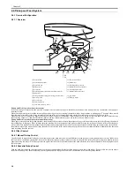
scanner motor, and high-voltage system and puts the printer unit in an error state.
a) the reading of the main thermistor does not exceed 50 deg C within 2.34 sec after the start-up temperature control mechanism is started.
b) the CPU detects that the reading of the main thermistor remains 235 deg C or more for 1 sec continuously while fixing temperature control is under way.
c) the CPU detects that the reading of the main thermistor remains 100 deg C or less for 1.2 sec continuously while paper passage temperature control is under way;
or the CPU detects that the reading of the main thermistor remains 50 deg C or less for 0.3 sec continuously while between-sheets temperature control is under
way.
d) the CPU detects that the reading of the main thermistor remains less than 20 deg C for 0.3 sec continuously while fixing heater temperature control is under way.
e) the temperature of the main thermistor does not exceed 100 deg C within 20 sec after the start of start-up temperature control.
f) the CPU detects that the reading of the sub thermistor remains less than 35 deg C for 0.15 sec continuously while fixing heater temperature control is under way.
g) the CPU detects that the reading of the sub thermistor remains 320 deg C for 0.15 sec continuously while fixing heater temperature control is under way.
2.6 External and Controls
2.6.1 Power Supply
2.6.1.1 Backup Battery
2.6.1.1.1 Backup Battery
0012-3264
The machine's SCNT PCB are equipped with a lithium battery (1 pc. each) serving as a backup source of power in the event of a power shortage or when the power
plug is removed.
T-2-6
LISK OF EXPLOSION IF BATTERY IS REPLACED BY AN INCORRECT TYPE.
DISPOSE OF USED BATTERIES ACCORDING TO THE INSTRUCTIONS.
SCNT PCB
litium battery (3V,220mAh)
Life
5yr or more (with power plug removed)
Replacement
not possible in the field on its own.
Summary of Contents for LaserBase MF3220 Series
Page 1: ...Mar 31 2006 Service Manual MF3220 Series LaserBase MF3220 ...
Page 2: ......
Page 6: ......
Page 14: ...Contents ...
Page 15: ...Chapter 1 PRODUCT DESCRIPTION ...
Page 16: ......
Page 18: ......
Page 24: ......
Page 25: ...Chapter 2 TECHNICAL REFERENCE ...
Page 26: ......
Page 28: ......
Page 36: ......
Page 37: ...Chapter 3 DISASSEMBLY AND ASSEMBLY ...
Page 38: ......
Page 44: ......
Page 90: ......
Page 91: ...Chapter 4 MAINTENANCE AND INSPECTION ...
Page 92: ......
Page 94: ......
Page 105: ...Chapter 5 TROUBLESHOOTING ...
Page 106: ......
Page 108: ......
Page 117: ...Chapter 6 APPENDIX ...
Page 118: ......
Page 120: ......
Page 123: ...Mar 31 2006 ...
Page 124: ......

