Chapter 2
2-6
2.5 Fixing Unit
2.5.1 Overview/Configuration
2.5.1.1 Overview
0012-0915
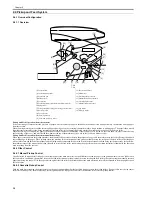
F-2-5
T-2-5
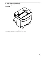
The machine's fixing system is an on-demand type, and its fixing assembly consists of the fixing film unit and the pressure roller: the fixing film has a built-in fixing
heater, thermistor, and thermal fuse.
The toner transferred to paper is heated by the fixing heater, which provides heat through the fixing film; the toner is forced under the pressure roller so that it is
fused into the fibers of the paper under both heat and pressure.
2.5.2 Protection Function
2.5.2.1 Protective Mechanisms
0012-0916
The machine is equipped with the following 3 types of protective mechanisms used to prevent its fixing heater from going awry.
1. protective mechanism by the CPU
2. protective mechanism by the fixing heater safety circuit
3. protective mechanism by the thermal fuse
1. Protective Mechanism by the CPU
The machine's CPU monitors the voltage of the fixing heater temperature detection signal from the main thermistor and the sub thermistor at all times, and
it cuts the power to the fixing heater if it finds that the fixing temperature appreciably exceeds a specific level.
When the fixing temperature abnormally increases and the voltage of the fixing heater temperature detection signal from the main thermistor drops to about
0.775 V (equivalent of 235 deg C) or less, the CPU causes the fixing heater drive signal to go Low and turns off the photo triac coupler, thus cutting power
to the fixing heater.
If the temperature of the fixing heater abnormally increases and the voltage of the fixing heater temperature detection signal from the sub thermistor reaches
about 2.779 V (equivalent of 320 deg C) or more, the CPU causes the fixing heater drive signal to go Low and turns off the photo triac couple, thus cutting
off the power to the fixing heater.
2. Protective Mechanism by the Fixing Heater Safety Circuit
The fixing heater safety circuit monitors the voltage of the fixing heater temperature detection signal from the main thermistor and the sub thermistor at all
times.
If the fixing temperature appreciably exceeds a specific level, the machine cuts off the power to the fixing heater regardless of the instructions from the CPU.
When the temperature of the fixing heater increases abnormally and the voltage of the fixing heater temperature detection signal of the main thermistor
reaches about 0.775 V (equivalent of 235 deg C) or less, the output of the comparator turns Low to turn off the relay, thus cutting off the power to the fixing
heater.
Likewise, if the temperature of the fixing heater increases abnormally and the voltage of the fixing heater temperature detection signal of the sub thermistor
reaches about 2.779 V (equivalent of 320 deg C) or more, the output of the comparator turns Low to turn off the transistor, thus turning off the relay and
cutting off the power to the fixing heater regardless of the relay drive signal from the CPU.
3. Protective Mechanism by the Thermal Fuse
If the temperature of the fixing heater increases abnormally and the temperature of the thermal fuse exceeds about 228 deg C, the thermal fuse starts to melt
to cut off the power to the fixing heater.
2.5.2.2 Detecting a Fault in the Fixing Assembly
0012-0917
The CPU identifies a fault in the fixing assembly for the following conditions (a. thorough g.) and operates as described:
1. the CPU causes the fixing heater drive signal to go Low to cut off the power to the fixing heater.
2. the CPU causes the relay drive signal to go Low to turn off the relay.
3. the CPU, if it detects a fault while printing is under way, discharges the paper being picked up or moved at the time, and immediately turns off the main motor,
[1] Fixing film unit
[2] Fixing heater
[3] Pressure roller
[1]
[3]
[2]
Summary of Contents for LaserBase MF3220 Series
Page 1: ...Mar 31 2006 Service Manual MF3220 Series LaserBase MF3220 ...
Page 2: ......
Page 6: ......
Page 14: ...Contents ...
Page 15: ...Chapter 1 PRODUCT DESCRIPTION ...
Page 16: ......
Page 18: ......
Page 24: ......
Page 25: ...Chapter 2 TECHNICAL REFERENCE ...
Page 26: ......
Page 28: ......
Page 36: ......
Page 37: ...Chapter 3 DISASSEMBLY AND ASSEMBLY ...
Page 38: ......
Page 44: ......
Page 90: ......
Page 91: ...Chapter 4 MAINTENANCE AND INSPECTION ...
Page 92: ......
Page 94: ......
Page 105: ...Chapter 5 TROUBLESHOOTING ...
Page 106: ......
Page 108: ......
Page 117: ...Chapter 6 APPENDIX ...
Page 118: ......
Page 120: ......
Page 123: ...Mar 31 2006 ...
Page 124: ......

