


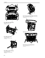


Chapter 3
3-37
F-3-234
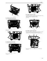
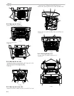
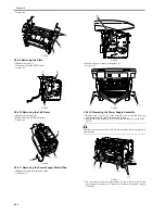
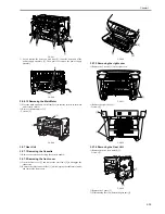
2) Remove the right cover [1].
- 2 screws [2]
F-3-235
3.5.6.4 Removing the left cover
0012-1718
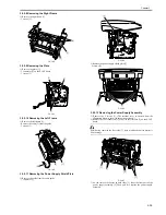
1) Remove the 2 screws [1] on the left cover.
F-3-236
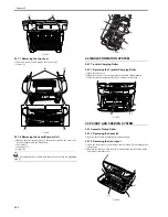
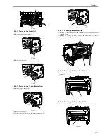
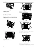
2) Remove the left cover [1].
- 2 screws [2]
F-3-237
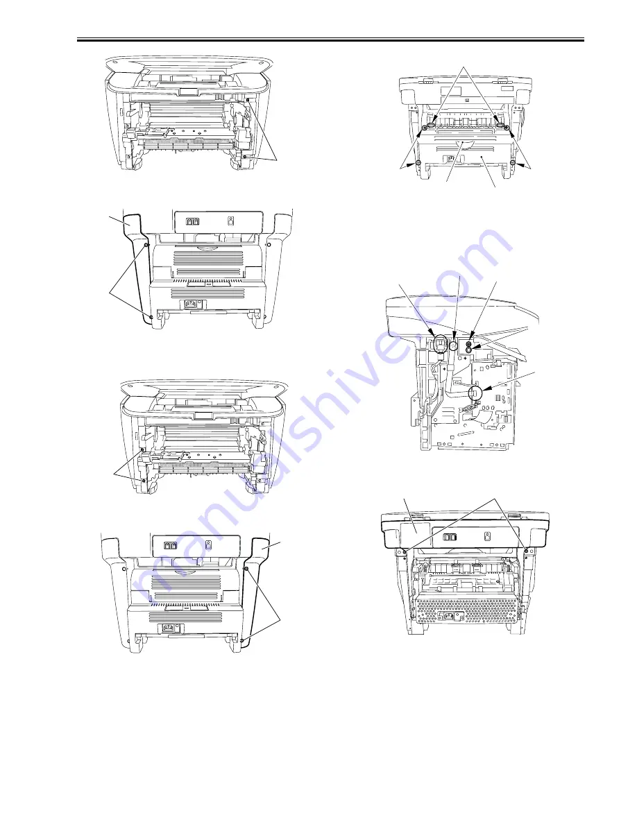
3.5.6.5 Removing the rear cover
0012-1719
1) Opening the face-up cover [1], and then lower the fixing pressure release
levers [2] on both sides and release the pressure.
2) Remove the rear cover [3] by sliding it to the rear.
- 4 screws [4]
F-3-238
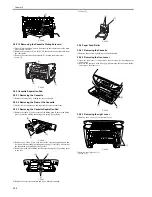
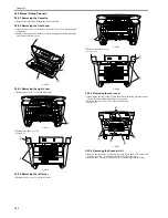
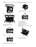
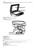
3.5.6.6 Removing the Scanner Unit
0012-1720
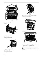
1) Remove the connector [1] and the flat cable [2] on the ECNT board, and
remove the screw [3]. (Remove the flat cable from the core.)
2) Remove the 2 screws [4] and the 2 pins [5] on the right and left sides.
F-3-239
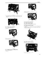
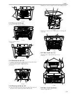
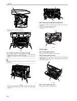
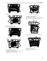
3) Remove the scanner unit [1] by sliding it to the rear and lifting it up.
- 2 screws [2]
F-3-240
3.5.6.7 Removing the top cover
0012-1721
1) Free the 2 claws [1], and remove the top cover [2].
- 2 screws [3]
[1]
[2]
[1]
[1]
[2]
[1]
[1]
[4]
[3]
[2]
[4]
[2]
[5]
[4]
[1]
[3]
[1]
[2]
Summary of Contents for LaserBase MF3220 Series
Page 1: ...Mar 31 2006 Service Manual MF3220 Series LaserBase MF3220 ...
Page 2: ......
Page 6: ......
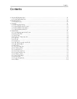
Page 14: ...Contents ...
Page 15: ...Chapter 1 PRODUCT DESCRIPTION ...
Page 16: ......
Page 18: ......
Page 24: ......
Page 25: ...Chapter 2 TECHNICAL REFERENCE ...
Page 26: ......
Page 28: ......
Page 36: ......
Page 37: ...Chapter 3 DISASSEMBLY AND ASSEMBLY ...
Page 38: ......
Page 44: ......
Page 90: ......
Page 91: ...Chapter 4 MAINTENANCE AND INSPECTION ...
Page 92: ......
Page 94: ......
Page 105: ...Chapter 5 TROUBLESHOOTING ...
Page 106: ......
Page 108: ......
Page 117: ...Chapter 6 APPENDIX ...
Page 118: ......
Page 120: ......
Page 123: ...Mar 31 2006 ...
Page 124: ......