Chapter 3
3-27
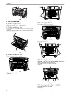
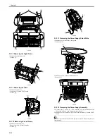
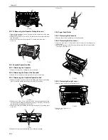
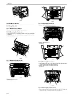
F-3-167
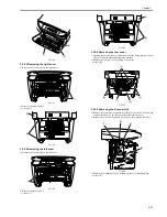
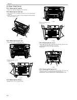
3) As you remove the bosses on both sides [1], lower the front part of the
power supply assembly [2]. Then pull it to remove the power supply
assembly.
F-3-168
3.5.1.13 Removing the Gear Unit
0012-1649
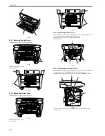
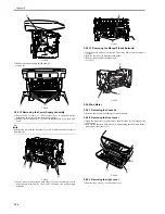
1) Remove the drive plate (small) [1].
- 2 screws [2]
F-3-169
2) Remove the 2 gears [1].
3) While freeing the claw, detach the gear unit [2].
F-3-170
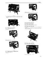
3.5.1.14 Removing the Tooth-Missing Gear
0012-1650
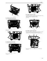
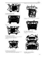
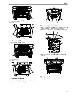
1) Remove the gear support [1].
- 2 screws [2]
F-3-171
2) Remove the spring [1].
3) While freeing the claw, detach the tooth-missing gear [2].
F-3-172
3.5.2 Cassette Pickup Solenoid
3.5.2.1 Removing the Cassette
0012-1656
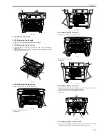
1) Remove the cassette by holding the cassette handle.
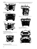
3.5.2.2 Removing the front cover
0012-1657
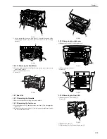
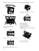
1) Open the front cover [1] and remove the arm claws [2] to disengage the
connection.
2) Remove the shafts on both sides [3] while warping the shaft arms inside,
and remove the front cover.
F-3-173
3.5.2.3 Removing the right cover
0012-1658
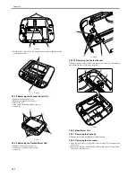
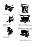
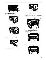
1) Remove the 2 screws [1] on the right cover.
F-3-174
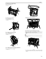
2) Remove the right cover [1].
[1]
[2]
[2]
[3]
[1]
[1]
[2]
[2]
[1]
[2]
[1]
[2]
[1]
[2]
[1]
[1]
[3]
[3]
[2]
[1]
Summary of Contents for LaserBase MF3220 Series
Page 1: ...Mar 31 2006 Service Manual MF3220 Series LaserBase MF3220 ...
Page 2: ......
Page 6: ......
Page 14: ...Contents ...
Page 15: ...Chapter 1 PRODUCT DESCRIPTION ...
Page 16: ......
Page 18: ......
Page 24: ......
Page 25: ...Chapter 2 TECHNICAL REFERENCE ...
Page 26: ......
Page 28: ......
Page 36: ......
Page 37: ...Chapter 3 DISASSEMBLY AND ASSEMBLY ...
Page 38: ......
Page 44: ......
Page 90: ......
Page 91: ...Chapter 4 MAINTENANCE AND INSPECTION ...
Page 92: ......
Page 94: ......
Page 105: ...Chapter 5 TROUBLESHOOTING ...
Page 106: ......
Page 108: ......
Page 117: ...Chapter 6 APPENDIX ...
Page 118: ......
Page 120: ......
Page 123: ...Mar 31 2006 ...
Page 124: ......


