


Chapter 8
8-6
8.1.6 Fixing Block
0019-5017
imageRUNNER C1022 / imageRUNNER C1022i / Color imageRUNNER C1030 / Color imageRUNNER C1030iF
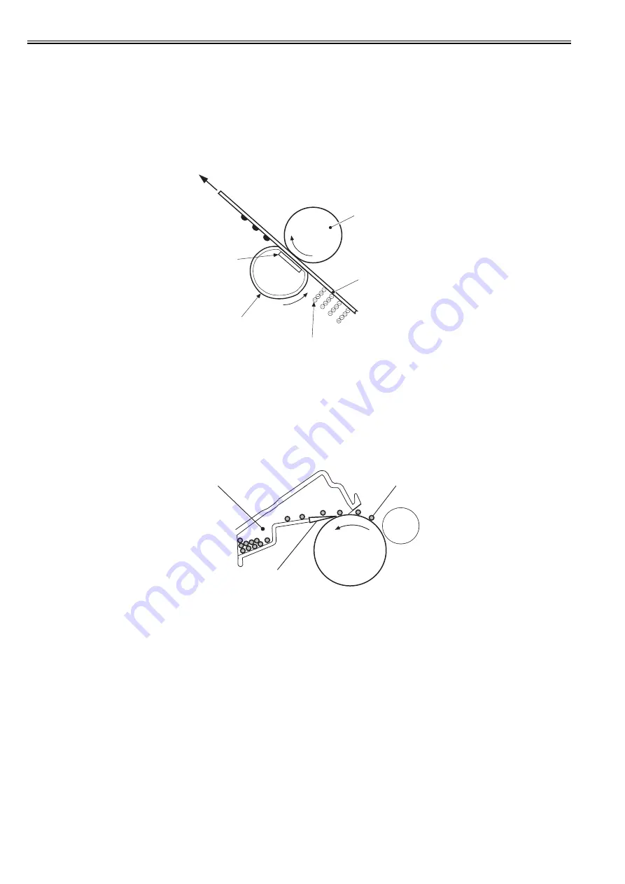
In this block, a toner image is fixed on paper.
The toner image transferred to the paper can be smeared easily by hands since it is only attracted to the paper by a static electricity.
When pressure and heat are applied to the paper and toner image, the toner image melts with mixed colors and becomes a permanent printed image (on-demand
fixing).
Step 9: Fixing
When the paper with toner is transported between the fixing sleeve and the pressure roller, the toner is melted by heat and fixed to the paper by pressure.
For the fixing heater, the machine uses a ceramic heater with lower heat, which warms up quickly. The feature of this heater is that the wait time is short and thus
energy saving is realized.
F-8-11
8.1.7 Cleaning Block
0019-5018
imageRUNNER C1022 / imageRUNNER C1022i / Color imageRUNNER C1030 / Color imageRUNNER C1030iF
In this block, the residual toner on the photosensitive drum is removed.
When transfer is performed, a part of the toner image on the photosensitive drum is not sometimes transferred and remains on the drum. This remaining toner is
called residual toner.
Removing the residual toner keeps a clear image in the subsequent print operation.
Step 10: Drum cleaning
The residual toner on the photosensitive drum is scraped by the cleaner blade, and then collected into the waste toner container.
F-8-12
Fixing sleeve
Fixing heater
Pressure roller
Toner
Paper
Waste toner container
Cleaner blade
Photosensitive
drum
residual toner
Summary of Contents for imageRUNNERC1022
Page 2: ......
Page 6: ......
Page 19: ...Chapter 1 Introduction ...
Page 20: ......
Page 93: ...Chapter 2 Installation ...
Page 94: ......
Page 96: ......
Page 111: ...Chapter 3 Basic Operation ...
Page 112: ......
Page 114: ......
Page 119: ...Chapter 4 Main Controller ...
Page 120: ......
Page 122: ......
Page 135: ...Chapter 5 Original Exposure System ...
Page 136: ......
Page 138: ......
Page 151: ...Chapter 6 Original Feeding System ...
Page 152: ......
Page 154: ......
Page 170: ......
Page 171: ...Chapter 7 Laser Exposure ...
Page 172: ......
Page 174: ......
Page 184: ......
Page 185: ...Chapter 8 Image Formation ...
Page 186: ......
Page 188: ......
Page 222: ......
Page 223: ...Chapter 9 Pickup and Feed System ...
Page 224: ......
Page 259: ...Chapter 10 Fixing System ...
Page 260: ......
Page 262: ......
Page 268: ...Chapter 10 10 6 ...
Page 279: ...Chapter 11 External and Controls ...
Page 280: ......
Page 311: ...Chapter 12 e Maintenance imageWARE Remote ...
Page 312: ......
Page 314: ......
Page 323: ...Chapter 12 12 9 F 12 27 ...
Page 349: ...Chapter 13 Maintenance and Inspection ...
Page 350: ......
Page 352: ......
Page 354: ......
Page 355: ...Chapter 14 Measurement and Adjustments ...
Page 356: ......
Page 358: ......
Page 361: ...Chapter 15 Correcting Faulty Images ...
Page 362: ......
Page 364: ......
Page 385: ...Chapter 16 Error Code ...
Page 386: ......
Page 388: ......
Page 399: ...Chapter 16 16 11 ...
Page 400: ......
Page 401: ...Chapter 17 Special Management Mode ...
Page 402: ......
Page 404: ......
Page 411: ...Chapter 17 17 7 ...
Page 412: ......
Page 413: ...Chapter 18 Service Mode ...
Page 414: ......
Page 492: ......
Page 493: ...Chapter 19 Upgrading ...
Page 494: ......
Page 496: ......
Page 500: ...Chapter 19 19 4 3 Click Next F 19 4 4 Select a USB connected device and click Next F 19 5 ...
Page 501: ...Chapter 19 19 5 5 Click Start F 19 6 6 Click Yes F 19 7 Download will be started F 19 8 ...
Page 504: ...Chapter 19 19 8 4 Select a USB connected device and click Next F 19 12 5 Click Start F 19 13 ...
Page 506: ...Chapter 19 19 10 ...
Page 507: ...Chapter 20 Service Tools ...
Page 508: ......
Page 510: ......
Page 514: ......
Page 515: ...Appendix ...
Page 516: ......
Page 532: ......
Page 533: ...Oct 29 2010 ...
Page 534: ......


