Chapter 11
11-7
11.4 Power Supply
11.4.1 Power Supply
11.4.1.1 Low-voltage Power Unit
0020-2570
imageRUNNER C1022 / imageRUNNER C1022i / Color imageRUNNER C1030 / Color imageRUNNER C1030iF
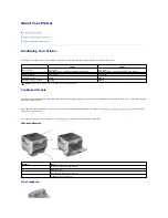
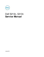
The low-voltage power PCB is to convert AC into DC covering the DC loads.
F-11-3
The low-voltage power PCB is partially activated as soon as plugged in the electrical outlet. When turning ON the power switch (SW4), whole low-voltage power
supply works.
The AC power is then converted into +24V, +5V and +3.3V covering each of machine DC loads. The following are the main loads for each power.
+24V:
Main controller PCB, high-voltage power PCB, Motors, solenoids, fans, reverse unit, and ADF
+5V:
Main controller PCB, driver PCB, laser driver PCB, high-voltage power PCB, memory controller PCB, color displacement/density sensor, and control
panel
+3.3V:
DC controller PCB, main controller PCB, driver PCB, high-voltage power PCB, memory controller PCB, sensor (photo interrupter), environment sensor,
fixing unit, control panel, reverse unit, and ADF
CPU
(IC1001)
Noise filter
Fuse
Power switch
Fuse
Noise filter
Low-voltage power circuit
Remote switch
control circuit
Zero crossing
circuit
24V ON/OFF circuit
24V generation
circuit
5V generation circuit
3.3V generation circuit
Machine power supply
voltage detection circuit
ASIC
(IC1010)
PS100V
3.3V
5V
24VA
PSREM24V
ZEROX
PSOFF
/PSSWOPEN
FSRD
RLD-
DC controller
PCB
Driver PCB
Front cover detection switch
24VA
24VB
24VA
24VB
3.3V 5V
RLD+
Fixing unit
3.3V
Reverse unit
3.3V
24VB
Pickup motor Drum motor
ETB motor Fixing motor
Solenoids
24VB
Photointerrupters
3.3V
High-voltage power PCB
3.3V
24VB
5V
Fan
Scanner motor
24VA
Laser driver PCB
5V
5V
3.3V
Memory controller PCB
Environment sensor
Photointerrupters
3.3V
5V
3.3V
Main controller PCB
Control panel
ADF
Fixing
control
circuit
Low-voltage power PCB
Color displacement/density sensor
SW4
FU3801
FU3901
Protective circuit
Summary of Contents for imageRUNNERC1022
Page 2: ......
Page 6: ......
Page 19: ...Chapter 1 Introduction ...
Page 20: ......
Page 93: ...Chapter 2 Installation ...
Page 94: ......
Page 96: ......
Page 111: ...Chapter 3 Basic Operation ...
Page 112: ......
Page 114: ......
Page 119: ...Chapter 4 Main Controller ...
Page 120: ......
Page 122: ......
Page 135: ...Chapter 5 Original Exposure System ...
Page 136: ......
Page 138: ......
Page 151: ...Chapter 6 Original Feeding System ...
Page 152: ......
Page 154: ......
Page 170: ......
Page 171: ...Chapter 7 Laser Exposure ...
Page 172: ......
Page 174: ......
Page 184: ......
Page 185: ...Chapter 8 Image Formation ...
Page 186: ......
Page 188: ......
Page 222: ......
Page 223: ...Chapter 9 Pickup and Feed System ...
Page 224: ......
Page 259: ...Chapter 10 Fixing System ...
Page 260: ......
Page 262: ......
Page 268: ...Chapter 10 10 6 ...
Page 279: ...Chapter 11 External and Controls ...
Page 280: ......
Page 311: ...Chapter 12 e Maintenance imageWARE Remote ...
Page 312: ......
Page 314: ......
Page 323: ...Chapter 12 12 9 F 12 27 ...
Page 349: ...Chapter 13 Maintenance and Inspection ...
Page 350: ......
Page 352: ......
Page 354: ......
Page 355: ...Chapter 14 Measurement and Adjustments ...
Page 356: ......
Page 358: ......
Page 361: ...Chapter 15 Correcting Faulty Images ...
Page 362: ......
Page 364: ......
Page 385: ...Chapter 16 Error Code ...
Page 386: ......
Page 388: ......
Page 399: ...Chapter 16 16 11 ...
Page 400: ......
Page 401: ...Chapter 17 Special Management Mode ...
Page 402: ......
Page 404: ......
Page 411: ...Chapter 17 17 7 ...
Page 412: ......
Page 413: ...Chapter 18 Service Mode ...
Page 414: ......
Page 492: ......
Page 493: ...Chapter 19 Upgrading ...
Page 494: ......
Page 496: ......
Page 500: ...Chapter 19 19 4 3 Click Next F 19 4 4 Select a USB connected device and click Next F 19 5 ...
Page 501: ...Chapter 19 19 5 5 Click Start F 19 6 6 Click Yes F 19 7 Download will be started F 19 8 ...
Page 504: ...Chapter 19 19 8 4 Select a USB connected device and click Next F 19 12 5 Click Start F 19 13 ...
Page 506: ...Chapter 19 19 10 ...
Page 507: ...Chapter 20 Service Tools ...
Page 508: ......
Page 510: ......
Page 514: ......
Page 515: ...Appendix ...
Page 516: ......
Page 532: ......
Page 533: ...Oct 29 2010 ...
Page 534: ......