


Chapter 18
18-73
18.5.5.2 PANEL List
0025-8865
Color imageRUNNER C1030 / Color imageRUNNER C1030iF
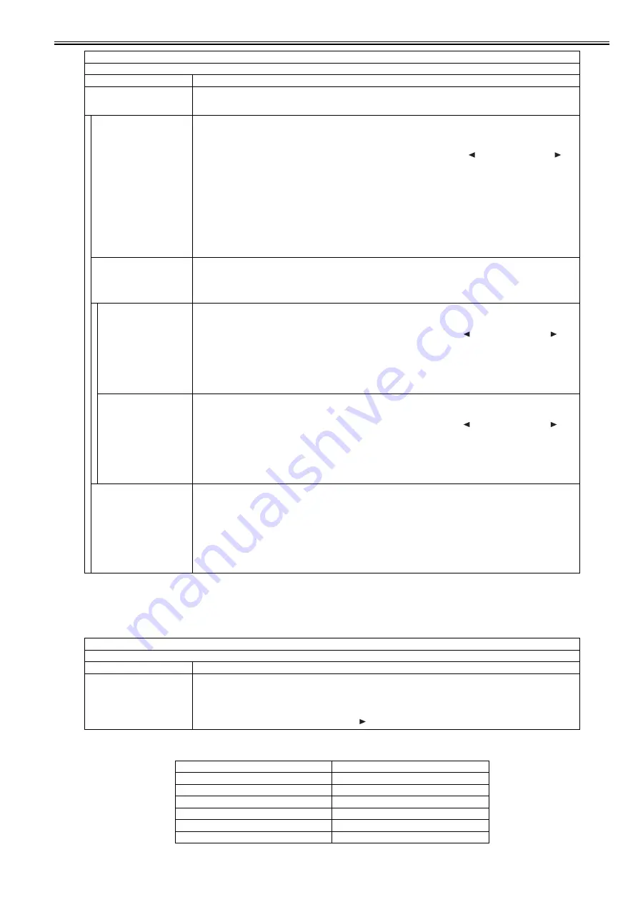
<PANEL>
T-18-124
T-18-125
FLICKER CHECK START
Flicker check
Adjust and check the LCD flicker. Adjustment can be made by changing the setting value.
Perform operation in the order of "FLICKER ADJUST -> FLICEKR MIN/MAX -> FLICKER CONFIRM".
FLICKER ADJUST
Adjust the setting value.
[Adjustment method]
1) Press the OK key.
2) In the setting value entry screen displayed, press the OK key again.
3) Increase or decrease the setting value to minimize flicker in the flicker screen displayed. ( key: The value decreases. key:
The value increases.)
4) When pressing the OK key, the setting value is displayed in the setting value input screen.
5) Press the Return key and complete adjustment.
Setting range: 0 to 33
[Factory setting value: Varies depending on the machine]
[Value after clearing of RAM data: 15]
MEMO:
A setting value can be entered in the setting value entry screen, using numeric keys. However, to reflect the setting value, it is
necessary to display the flicker screen once after the value is entered.
FLICKER MIN/MAX
Specify the minimum/maximum setting value to make an adjustment.
MEMO:
After setting is completed, the setting value which was displayed in FLICKER ADJUST is changed to the average value of MIN
and MAX.
MIN
Set the minimum setting value.
[Adjustment method]
1) Press the OK key.
2) Increase/decrease the setting value to minimize flicker in the flicker screen displayed. ( key: The value decreases. key:
The value increases.)
3) When pressing the OK key, the setting value is displayed.
4) Press the Return key and complete adjustment.
[Factory setting value: Varies depending on the machine]
[Value after clearing of RAM data: 10]
MAX
Set the maximum setting value.
[Adjustment method]
1) Press the OK key.
2) Increase/decrease the setting value to minimize flicker in the flicker screen displayed. ( key: The value decreases. key:
The value increases.)
3) When pressing the OK key, the setting value is displayed.
4) Press the Return key and complete adjustment.
[Factory setting value: Varies depending on the machine]
[Value after clearing of RAM data: 20]
FLICKER CONFIRM
Check the setting.
[Adjustment method]
1) Press the OK key.
2) In the setting value entry screen displayed, press the OK key again.
3) When pressing the OK key after checking the flicker screen, the setting value entry screen is displayed.
4) Press the Return key and complete checking.
Setting range: 0 to 255
[Factory setting value: Varies depending on the machine]
[Value after clearing of RAM data: 200]
TESTMODE > PANEL
Key, wheel, LCD, LED, and flicker check
Sub item
Description
KEY CHECK START
Key check
Check the operation of the key on the control panel.
The following table shows information displayed when pressing each key.
When pressing the OK key after operation check, OK or NG is displayed in the following condition.
OK: Operation was correctly performed for all keys.
NG: A failure occurred to key operation. (Clicking the key displays the keys which have not been pressed sequentially.)
Type of Key
Character String Displayed
Main Menu key
MAIN
Custom key 1
COPY
Custom key 2
SEND
Status monitor/Cancel key
JOB
Left any key
MENU-L
Right any key
MENU-R
TESTMODE > PANEL
Key, wheel, LCD, LED, and flicker check
Sub item
Description
Summary of Contents for imageRUNNERC1022
Page 2: ......
Page 6: ......
Page 19: ...Chapter 1 Introduction ...
Page 20: ......
Page 93: ...Chapter 2 Installation ...
Page 94: ......
Page 96: ......
Page 111: ...Chapter 3 Basic Operation ...
Page 112: ......
Page 114: ......
Page 119: ...Chapter 4 Main Controller ...
Page 120: ......
Page 122: ......
Page 135: ...Chapter 5 Original Exposure System ...
Page 136: ......
Page 138: ......
Page 151: ...Chapter 6 Original Feeding System ...
Page 152: ......
Page 154: ......
Page 170: ......
Page 171: ...Chapter 7 Laser Exposure ...
Page 172: ......
Page 174: ......
Page 184: ......
Page 185: ...Chapter 8 Image Formation ...
Page 186: ......
Page 188: ......
Page 222: ......
Page 223: ...Chapter 9 Pickup and Feed System ...
Page 224: ......
Page 259: ...Chapter 10 Fixing System ...
Page 260: ......
Page 262: ......
Page 268: ...Chapter 10 10 6 ...
Page 279: ...Chapter 11 External and Controls ...
Page 280: ......
Page 311: ...Chapter 12 e Maintenance imageWARE Remote ...
Page 312: ......
Page 314: ......
Page 323: ...Chapter 12 12 9 F 12 27 ...
Page 349: ...Chapter 13 Maintenance and Inspection ...
Page 350: ......
Page 352: ......
Page 354: ......
Page 355: ...Chapter 14 Measurement and Adjustments ...
Page 356: ......
Page 358: ......
Page 361: ...Chapter 15 Correcting Faulty Images ...
Page 362: ......
Page 364: ......
Page 385: ...Chapter 16 Error Code ...
Page 386: ......
Page 388: ......
Page 399: ...Chapter 16 16 11 ...
Page 400: ......
Page 401: ...Chapter 17 Special Management Mode ...
Page 402: ......
Page 404: ......
Page 411: ...Chapter 17 17 7 ...
Page 412: ......
Page 413: ...Chapter 18 Service Mode ...
Page 414: ......
Page 492: ......
Page 493: ...Chapter 19 Upgrading ...
Page 494: ......
Page 496: ......
Page 500: ...Chapter 19 19 4 3 Click Next F 19 4 4 Select a USB connected device and click Next F 19 5 ...
Page 501: ...Chapter 19 19 5 5 Click Start F 19 6 6 Click Yes F 19 7 Download will be started F 19 8 ...
Page 504: ...Chapter 19 19 8 4 Select a USB connected device and click Next F 19 12 5 Click Start F 19 13 ...
Page 506: ...Chapter 19 19 10 ...
Page 507: ...Chapter 20 Service Tools ...
Page 508: ......
Page 510: ......
Page 514: ......
Page 515: ...Appendix ...
Page 516: ......
Page 532: ......
Page 533: ...Oct 29 2010 ...
Page 534: ......


