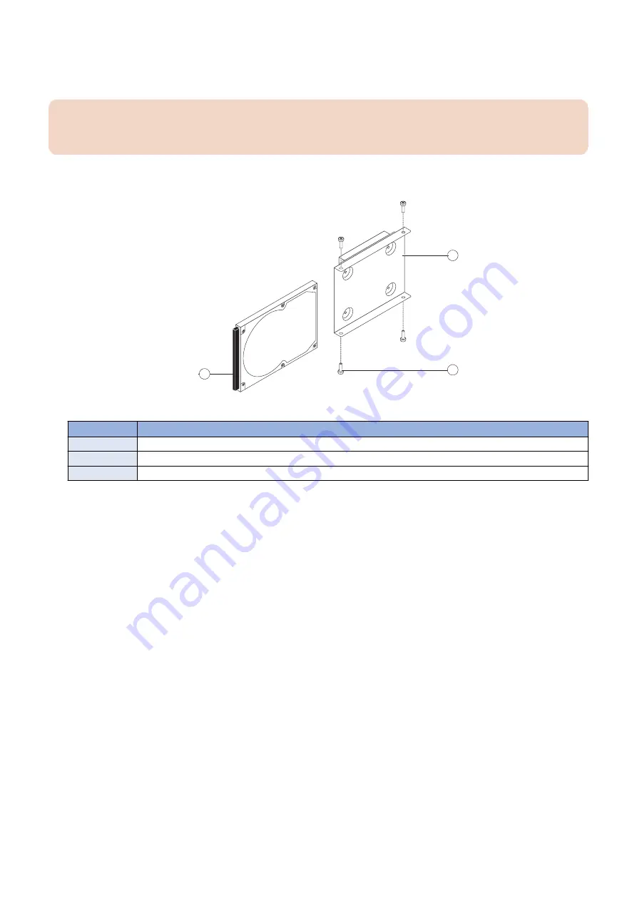
7. If you are replacing the HDD with a new HDD, remove the HDD from its bracket.
Remove the four screws that secure the HDD to the HDD bracket (see below figure). Remove the HDD bracket and set it
aside so that you can replace it later.
IMPORTANT:
Make sure to support the HDD as you remove the screws. Do not loosen or remove the screws on the HDD covers.
Loosening or removing these screws will break the seal and void the HDD warranty.
Do not touch the HDDs with magnetic objects (such as magnetic screwdrivers), and avoid placing magneticsensitive items,
such as credit cards and employee ID cards, near the HDDs.
1
2
3
Figure 28: Removing the HDD bracket
No.
Name
1
HDD (connector side)
2
HDD bracket
3
Screw (1 of 4)
8. Place the HDD in an antistatic bag.
Replacement HDDs are shipped without any pre-installed system software. You must install the appropriate system software.
● To replace the HDD
1. If you are installing a new HDD, unpack the drive. If you are not installing a new HDD, skip to step 4.
Do not drop, jar, or bump the HDD. Do not touch the HDD with magnetic objects or place magnetic-sensitive items near the
HDD.
2. Place the HDD inside the HDD bracket, and align the two holes on either side of the HDD with the holes in the bracket.
Position the HDD inside the HDD bracket as shown in
“To remove the HDD” on page 41
.
3. Replace the four screws that attach the bracket to the HDD.
Make sure that you use the same screws that you removed earlier.
4. Position the HDD assembly inside the chassis, as shown in
“To remove the HDD” on page 41
.
Position the lower edge of the HDD bracket over the mounting posts in the chassis, and press down firmly to engage the
posts.
5. Using the two screws that you removed earlier, secure the HDD assembly to the chassis.
6. Connect the SATA data cable to the SATA data connector on the HDD. Make sure that the other end of the cable is
connected to SATA0 on the motherboard.
7. Connect the SATA power cable connector to the SATA power connector on the HDD.
The cable connector is keyed to fit only one way.
8. Reassemble the
imagePASS
(see
“To reinstall and verify the imagePASS” on page 44
9. Connect the external cables that you removed from the
imagePASS
.
3. REPLACING PARTS
43
Summary of Contents for imagePASS-R1
Page 6: ...Introduction 1 Introduction 2 Specifications 7 ...
Page 15: ...Using the imagePASS 2 Using the imagePASS 11 ...
Page 19: ...REPLACING PARTS 3 Replacing Parts 15 ...
Page 51: ...INSTALLING SYSTEM SOFTWARE 4 Installing System Software 47 ...


