background image

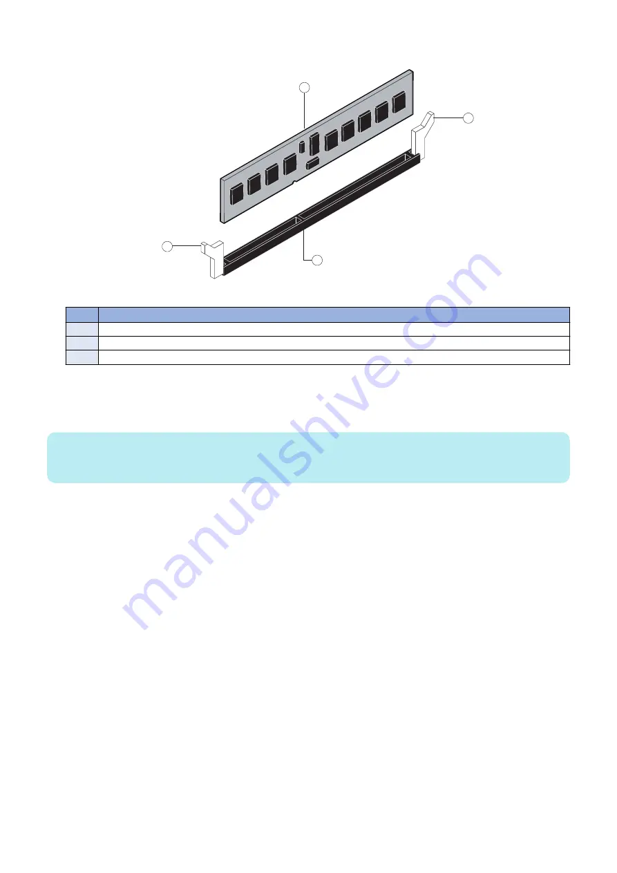
2. To release a DIMM, push outward on the levers on each side of the DIMM (see below figure).

1

2

3

1

Figure 11: Releasing a DIMM

No.

Name

1

Lever

2

DIMM

3

Slot notch

3. Lift the DIMM straight out of the slot.

4. To replace a DIMM, position the DIMM in the DIMM-A0 slot and press the DIMM straight down into the slot, so that

the levers lock the DIMM into place (see above figure).

NOTE:

DIMM fits in the slot only one way. The notch on the bottom of the DIMM should line up with the notch in the slot. Make sure that
the levers close securely around the ends of the DIMM and that the DIMM is fully seated in its slot.

5. Reassemble the 

imagePASS

 and verify its functionality (see 

“Restoring imagePASS functionality after service” on

page 44

).

■ Motherboard

This section describes the battery and default jumper settings on the 

imagePASS

 motherboard, as well as procedures for removing

and replacing the motherboard.
If you are replacing the motherboard with a new one, ask the site administrator for the Fiery ID to unlock the Fiery User Data
Encryption. (see 

“How to obtain the Fiery password” on page 9

)

By unlocking the encryption, the new motherboard can read the necessary information and user data stored on the HDD. (see

“Unlocking the HDD” on page 9

The default Fiery ID for User Data Encryption is the Fiery password printed on the Configuration Page.
For details, see 

“How to obtain the Fiery password” on page 9

. The site administrator can change the Fiery ID using Configure

WebTools (by selecting Security > User Data Encryption).

● Battery

The battery is located on the motherboard. Spare batteries are not provided by your authorized service/support center.
If you must replace the battery, use a 3V manganese dioxide lithium coin cell battery (Panasonic CR2032 or equivalent).

3. REPLACING PARTS

23

Summary of Contents for imagePASS-R1

Page 1: ...SERVICE MANUAL imagePASS R1 Canon December 2 2020 Rev 1 COPYRIGHT 2020 CANON INC CANON imagePASS R1 Rev 1 PRINTED IN U S A ...

Page 2: ...ademarks and service marks of Mopria Alliance Inc in the United States and other countries Unauthorized use is strictly prohibited Apple AppleTalk Bonjour iPad iPhone iPod touch Mac OS X and Safari are trademarks of Apple Inc Microsoft Windows Windows Vista Windows Server Internet Explorer Microsoft Edge Excel and PowerPoint are either registered trademarks or trademarks of Microsoft Corporation i...

Page 3: ...s The following symbols are used throughout this Service Manual Symbols Explanation Symbols Explanation Check 1x Remove the claw Check visually 1x Insert the claw Check a sound Push the part 1x Disconnect the connector Connect the power cable 1x Connect the connector Disconnect the power cable 1x Remove the cable wire from the cable guide or wire saddle Turn on the power 1x Install the cable wire ...

Page 4: ...gnal is High while 0 is used to indicate Low The voltage value however differs from circuit to circuit In addition the asterisk as in DRMD indicates that the DRMD signal goes on when 0 In practically all cases the internal mechanisms of a microprocessor cannot be checked in the field Therefore the operations of the microprocessors used in the machines are not discussed they are explained in terms ...

Page 5: ...rting shutting down rebooting and restarting the imagePASS 11 3 REPLACING PARTS 14 Replacing Parts 15 Overview 15 Accessing the imagePASS 18 Checking imagePASS internal connections 19 Removing and replacing imagePASS components 20 Restoring imagePASS functionality after service 44 4 INSTALLING SYSTEM SOFTWARE 46 Installing System Software 47 System software installation reminders 47 Backing up and...

Page 6: ...Introduction 1 Introduction 2 Specifications 7 ...

Page 7: ...agePASS About this document This service document describes how to install imagePASS system software and how to service the imagePASS hardware It is not intended for customer use Information about the printer network remote computers software applications and imagePASS operating system is not included in this document Illustrations In this document illustrations reflect the version of the imagePAS...

Page 8: ...g printing The interpreter rasterizes the page description file and compresses the image pattern into memory using compression technology The interpreter outputs the compressed raster data through the image frame buffer memory to the printer interface board The raster data is sent to the printer which then renders the image on paper at maximum speed Before you service the imagePASS Before you serv...

Page 9: ...strator Do not assign an IP address to the imagePASS Only the site administrator should assign an IP address to a network device including the imagePASS If you enter an incorrect IP address for the imagePASS errors may occur on connected devices Handling boards When handling a printed circuit board do not bend it Hold it by opposing edges rather than by the corners Handling the hard disk drive To ...

Page 10: ...printer is most likely not static free and electrostatic discharge could occur Do the following to avoid damage due to electrostatic discharge Work on a grounded antistatic mat Wear an antistatic wristband attached to the same location as the antistatic mat Before you remove an electronic component from the shipping box touch a metal area of the printer to discharge static from your body After you...

Page 11: ...s the main disconnect device Ensure that the power outlet is located installed near the equipment and is easily accessible Lithium battery notice CAUTION There is a danger of explosion if the battery is replaced with an incorrect type Replace a battery only with the same type recommended by the manufacturer Dispose of used batteries according to local regulations Short circuit protection WARNING T...

Page 12: ...00Base TX 10Base T 4 Rear Ports USB2 0 2 Rear Ports USB3 0 Network protocols TCP IP FTP SMTP POP3 HTTP SNMP LDAP SLP SMB LPD IPP WS Discovery Bonjour Direct Mobile Printing Port9100 SNTP 802 1X DHCP DNS NTP Direct Print format PDF1 7 EPS TIFF6 JDF1 4 JMF OP VDP FreeForm v1 v2 1 Fiery Print Controller Standard Features Fiery Command WorkStation6 Paper Catalog Fiery Spot On Fiery Re mote Scan Fiery ...

Page 13: ...3 2013 EAC Republic of Belarus Republic of Kazakhstan Tajikistan Kyrgyzstan and Armenia CCC China System Software Item Ver System Software Fiery System 1 01 User Software Item Ver PS PrinterDriver 6 3 011 0 Win Mac PPD File 2020 10 28 Win Job Properties 3 5 0 45 Mac X Job Properties 3 5 0 045 Win Mac Impose Compose 6 0 0 27 Win Mac Command WorkStation 6 5 0 54 Win Mac Fiery Remote Scan 6 7 0 26 Wi...

Page 14: ...stem software or restore factory default settings the administrator password will be replaced by Fiery 1 Use Fiery 1 to log on to the imagePASS and change the password Unlocking the HDD HDD of imagePASS is Encryption If the motherboard has been replaced Unlocking the HDD so that data in the HDD can be accessed Unlocking the HDD go to WebTools and enter Fiery password 1 Obtaining the Fiery Password...

Page 15: ...Using the imagePASS 2 Using the imagePASS 11 ...

Page 16: ...e imagePASS Start page will also print automatically when the imagePASS is ready for use NOTE If the imagePASS does not start up within 15 minutes see the Startup section of Table Table 1 Causes and solutions when printer does not print on page 76 To shut down the imagePASS 1 Make sure that the imagePASS is not receiving processing or printing any jobs 2 Make sure that the printer is not in use 3 ...

Page 17: ...magePASS Tools menu To restart the imagePASS 1 Make sure that the imagePASS is not receiving processing or printing jobs 2 From the printer control panel press the Home button If the Fiery icon does not appear on the copier touch panel press the arrow at the lower right 2 Using the imagePASS 12 ...

Page 18: ...3 From the printer touch panel select Fiery Tools Restart Server Figure 3b The imagePASS Tools menu 2 Using the imagePASS 13 ...

Page 19: ...REPLACING PARTS 3 Replacing Parts 15 ...

Page 20: ...s imagePASS connector panel and LED diagnostic codest on page 17 Accessing the imagePASS Accessing the imagePASS on page 18 Cable connections Checking imagePASS internal connections on page 19 Removing and replacing imagePASS components Removing and replacing imagePASS components on page 20 IMPORTANT When performing the procedures described in this chapter see Tools you will need on page 3 and Pre...

Page 21: ...sis cover 2 Printer interface board 3 CPU cooling assembly 4 4GB DIMM 5 3 3GHz CPU 6 Security chip 7 Battery 8 Motherboard 9 500GB SATA HDD hard disk drive 10 HDD bracket 11 Chassis fan 12 Chassis fan guard 13 Service board 14 HDD SATA data cable 15 10 pin power button cable 16 Service board cable 3 REPLACING PARTS 16 ...

Page 22: ...anel No Name 1 Type A USB2 0 ports x2 2 Type A USB2 0 ports x2 3 Type A USB3 0 ports x2 4 Printer interface connector 5 Power connector 6 Network port Upper RJ 45 7 Crossover Ethernet connector 8 Duct 9 Power switch During startup the imagePASS advances through a standard diagnostic sequence Each diagnostic code flashes rapidly on the LED display during this sequence until the imagePASS reaches Id...

Page 23: ...For details see Precautions on page 4 To access the imagePASS 1 Make sure that the imagePASS is not receiving processing or printing any jobs 2 Make sure that the printer is not in use and power off the printer using the main power switch on the front Wait for the printer and the imagePASS to power off completely 3 Move the imagePASS power switch to the OFF O position 4 Remove all external cables ...

Page 24: ...urface so that the internal components are facing up 3 Make sure that the battery is properly installed see Battery on page 23 4 Inspect the HDD data cable to make sure that it is intact and connected to the SATA0 connector on the motherboard see Motherboard jumpers on page 25 NOTE The imagePASS will not boot up if the HDD data cable is connected to any other SATA connector on the motherboard Faul...

Page 25: ...nnector on motherboard 3 HDD data cable HDD data connector SATA0 connector on motherboard 4 Service board cable Service board connector Port 80 Header EFI GPIO Header connector on mother board J4 5 CPU fan cable CPU fan CPUFAN connector on motherboard CPU FAN J16 6 Chassis fan cable Chassis fan FRONT FAN connector on motherboard J30 Removing and replacing imagePASS components Before replacing cost...

Page 26: ...erface between the imagePASS and the printer The printer interface board processes the image data and sends it to the printer through the printer interface cable It is installed in PCIE x16 slot on the motherboard IMPORTANT Make sure that the switch on the printer interface board is positioned to 1 3m side of the switch 2 3 4 1 Figure 9 Printer interface board No Name 1 Switch positioned to 1 3m 2...

Page 27: ...res the printer interface board to the chassis Insert the mounting screw through the chassis and into the hole on the board mounting bracket see To remove the printer interface board on page 21 Tighten the screw completely 3 Connect one end of the 10 pin power button cable to J351 connector on the printer interface board Connect the other end to the J11 connector on the motherboard The cable conne...

Page 28: ... jumper settings on the imagePASS motherboard as well as procedures for removing and replacing the motherboard If you are replacing the motherboard with a new one ask the site administrator for the Fiery ID to unlock the Fiery User Data Encryption see How to obtain the Fiery password on page 9 By unlocking the encryption the new motherboard can read the necessary information and user data stored o...

Page 29: ...e type anbefalt av apparatfabrikanten Brukte batterier kasseres i henhold til fabrikantens instruksjoner VARNING Explosionsfara vid felaktigt batteribyte Använd samma batterityp eller en ekvivalent typ som rekommenderas av apparat tillverkaren Kassera använt batteri enligt fabrikantens instruktion CUIDADO Existe peligro de explosión si la batería se sustituye por una batería del tipo incorrecto Su...

Page 30: ...he IP address is listed under the Network Setup section of the imagePASS Configuration page 2 In WebTools click the Configure tab 3 Type the administrator account in User name and the corresponding password in Password then click Log In You can enter Administrator or admin for the administrator account name On the Fiery Server Configuration page look for ID in the BIOS Setup section The alphanumer...

Page 31: ...B3 0 ports x2 9 Type A USB2 0 connector x2 10 Type A USB2 0 ports x2 Network port RJ 45 11 CPU and cooling assembly MS Mounting screws 12 24 pin power connector J24 13 4 pin power connector PWRCONN1 14 CPU fan connector CPU FAN J16 15 FRONT FAN connector J30 16 Service board connector Port 80 Header EFI GPIO Header J4 MS Mounting screws NOTE Any connectors not listed are not used Removing the moth...

Page 32: ...inter interface board on page 21 3 Remove the following cables attached to the motherboard Chassis fan cable HDD data cable 4 pin power cable 24 pin power cable Service board cable 10 pin power button cable For the location of each connector on the motherboard see To check cable connections on page 19 To remove the motherboard IMPORTANT Follow standard ESD and other safety precautions when handlin...

Page 33: ...If you are replacing the motherboard with a new motherboard remove the following from the old motherboard DIMM see DIMM on page 22 CPU see CPU and CPU cooling assembly on page 32 Security chip see Transferring the security chip on page 28 Transferring the security chip Transferring the security chip from the old motherboard to the new motherboard ensures that all customer purchased software option...

Page 34: ...e socket Make sure not to put stress on surrounding components IMPORTANT Do not rock the chip from side to side when removing it from the socket Doing so may result in permanent damage to the security chip 1 2 Figure 15 Removing the security chip from the motherboard No Name 1 Security chip 2 Motherboard 3 Inspect the security chip and carefully straighten any bent pins with needlenose pliers 3 RE...

Page 35: ... motherboard 1 If you are installing a new motherboard do the following Remove the security chip from the old motherboard and install it onto the new motherboard see Transferring the security chip on page 28 Install the DIMM s from the old motherboard onto the new motherboard see DIMM on page 22 Install the CPU from the old motherboard onto the new motherboard see CPU and CPU cooling assembly on p...

Page 36: ...lly tighten each screw before completely tightening any one screw Do not overtighten the screws doing so could damage traces on the motherboard Now you are ready to replace the remaining motherboard components to complete the motherboard installation To replace motherboard components 1 Replace the following cables to the motherboard see To check cable connections on page 19 10 pin power button cab...

Page 37: ...the Fiery password After all the attempts fails you will need to select to delete all data to restore to the factory default 4 Follow the on screen instructions to unlock the HDD After unlocking the HDD restart the Fiery server CPU and CPU cooling assembly The CPU is installed in a socket on the motherboard Before removing the CPU from its socket remove the motherboard from the chassis see Removin...

Page 38: ...ePASS as described on Accessing the imagePASS on page 18 2 Remove the motherboard components see To remove motherboard components from the motherboard on page 27 3 Remove the motherboard from the chassis see To remove the motherboard on page 27 Place the motherboard on a flat antistatic surface 4 Remove the CPU fan cable from motherboard connector CPU FAN 3 REPLACING PARTS 33 ...

Page 39: ...cooling assembly to the motherboard Partially loosen all the screws before loosening any one screw all the way Lift the cooling assembly off the CPU socket and set it aside 1 2 Figure 19 Removing the CPU cooling assembly No Name 1 Screw 1 of 4 2 Loosen each screw to this position 6 Unlock the CPU socket lever and raise it into the open position flex the lever away from the retention post and then ...

Page 40: ...cooling assembly on an existing CPU clean the contact surface of the CPU to remove any old thermal compound residue A thermal pad is preinstalled on the underside of the new CPU cooling assembly IMPORTANT Be sure to remove all thermal compound residue from the surface of the CPU It may help to scrape all the residue off the surface using the flat edge of a nonconductive tool Then use a lint free c...

Page 41: ...ove any protective material that may be covering the surface of the thermal pad Otherwise the CPU may overheat Align the four screws with the four screw posts Tighten the screws Partially tighten all the screws before tightening any one screw all the way 8 Connect the CPU fan cable to the motherboard connector CPU FAN The cable connector is keyed to fit only one way Make sure that the connector on...

Page 42: ...board The cable is keyed to fit in the connector only one way 5 Connect the free end of the service board cable to connector Port 80 Header EFI GPIO Header J4 on the motherboard The cable is keyed to fit in the connector only one way 6 Make sure that the service switches are set to the OFF position both switches are away from ON See imagePASS connector panel and LED diagnostic codest on page 17 7 ...

Page 43: ...of 4 2 Chassis fan 4 If you are removing the chassis fan in order to replace it with a new one remove the fan guard from the face of the fan see below figure To remove the plastic rivets that secure the fan guard to the fan use a flathead screwdriver to pry loose the rivet head while squeezing and pushing the locking end of the rivet with your fingers or a pair of pliers Set aside the fan guard an...

Page 44: ... the fan should face the motherboard and the fan cable should reach its connector on the motherboard 4 Align the four holes on the fan with the four holes in the chassis and replace the four rivets that secure the fan to the chassis see below figure Hold the fan firmly against the chassis and push each rivet all the way until it snaps into the locked position Make sure that the fan is tightly secu...

Page 45: ...t attach the power supply duct to the chassis Remove the remaining two screws Set the screws aside so that you can replace them later 7 Gently lift the power supply out of the chassis 2 1 Figure 26 Removing the power supply No Name 1 Power switch 2 Screw 1 of 4 To replace the power supply 1 If you are replacing the power switch locate the new power switch included with the replacement power supply...

Page 46: ...n page 47 Proper handling IMPORTANT Improper handling can damage the HDD Handle the HDD with extreme care Use standard ESD precautions when grounding yourself and the imagePASS Keep magnets and magnetic sensitive objects away from the HDD Do not remove the screws on top of the HDD Loosening these screws voids the warranty Never drop jar bump or put excessive pressure on the HDD Handle the HDD by t...

Page 47: ...D assembly to release its lower edge from the mounting posts in the chassis and then remove the HDD assembly from the chassis 1 2 Figure 27 Removing the HDD assembly No Name 1 Screw 1 of 2 2 HDD assembly 3 REPLACING PARTS 42 ...

Page 48: ... drop jar or bump the HDD Do not touch the HDD with magnetic objects or place magnetic sensitive items near the HDD 2 Place the HDD inside the HDD bracket and align the two holes on either side of the HDD with the holes in the bracket Position the HDD inside the HDD bracket as shown in To remove the HDD on page 41 3 Replace the four screws that attach the bracket to the HDD Make sure that you use ...

Page 49: ...lack is secured with a tie wrap IMPORTANT Improper connection of the internal power cables can damage the imagePASS Checking imagePASS internal connections on page 19 which includes To reinstall and verify the imagePASS on page 44 2 Replace the cover on the imagePASS Make sure that all cables are fully inside the chassis before you replace the cover Slide the cover until it engages the edge of the...

Page 50: ... to configure the date and time in Setup see To configure the system date and time on page 25 8 Before you leave the customer site verify the imagePASS operation Connect the imagePASS to the network see imagePASS connector panel and LED diagnostic codest on page 17 Ask the site administrator to check the Setup options see Configuration and Setup 3 REPLACING PARTS 45 ...

Page 51: ...INSTALLING SYSTEM SOFTWARE 4 Installing System Software 47 ...

Page 52: ...twork administrator Fonts Installing system software deletes all fonts that the customer has installed on the imagePASS Only resident fonts are restored during system software installation Use Command WorkStation to reinstall additional fonts To determine which additional fonts were downloaded to the imagePASS ask the site administrator to print the Font List before you format the HDD and again af...

Page 53: ...an Administrator can access Paper Catalog Setup 1 Click the Export icon and choose Export All If you want to export only some of the media entries you can select multiple entries in the Export Selected You can Shiftclick to select sequential entries or Ctrl click to select nonsequential entries 2 Navigate to a location on your computer or network where you want to save the ex ported database file ...

Page 54: ...ame network as the imagePASS and open a Web browser window NOTE Request the permission from the network administrator before you connect your computer to the network 2 In the URL field of the browser type the IP address or server name of the imagePASS and press Enter to access WebTools The IP address and server name are listed on the Configuration page 3 In WebTools click the Configure tab 4 Log o...

Page 55: ...t multiple entries in the Export Selected You can Shiftclick to select sequential entries or Ctrl click to select nonsequential entries 2 Navigate to a location on your computer or network where you want to save the exported database file 3 Enter a name for the database file and then click Save To access the Fiery System Restore from Command WorkStationk 1 Start Command WorkStation and login to th...

Page 56: ... device Bootable device is used for system restoration when a hardware failure occurs NOTE The minimum size required for the USB flash drive depends on the actual size of the backup file You can determine the size of the backup file by checking the Estimated size field in the Create USB Backup dialog box Prepare a USB flash drive with enough capacity NOTE Due to a file system restriction the maxim...

Page 57: ...em software Any Windows computer with Windows 8 or Windows 10 NOTE Security of PC may not be maintained when using Windows OS that Microsoft had ended support to It may become more vulnerable to security risks when installing system software on USB devices by FIB Fiery Installer Builder When installing the system software make sure to use FIB Fiery Installer Builder with the PC running Microsoft s...

Page 58: ...all imagePASS system software stored on a network location To download and install the Fiery Installer Builder 1 From your web browser access fiery efi com FIB 2 Sign in to the EFI Sales Portal If you do not have an account at EFI Sales Portal click Register now to create an account Activate your account using the activation link received in your mailbox and then Sign in Dashboard Analyst Service ...

Page 59: ...also click Start EFI Fiery Installer Builder IMPORTANT Do not exit the Fiery Installer Builder before it completes the startup process Exiting the Fiery Installer Builder at the startup process may cause a problem 2 If you are starting the Fiery Installer Builder for the first time the Select location window appears Specify the folder that you want to use to store the system software files You can...

Page 60: ...et 4 Click Add 5 At the Login the EFI Portal window enter your EFI Sales Portal account credentials and click Login Proceed to step 6 If you do not have the EFI Sales Portal account information click connect Fiery link and then log in to the imagePASS by using the following procedure 4 INSTALLING SYSTEM SOFTWARE 55 ...

Page 61: ...ord of the administrator and click Next NOTE Default User name and Password User name Admin Password Fiery password See How to obtain the Fiery password on page 9 Contact the site administrator for the administrator s account information 6 At the Select a Brand window select Canon and click Next 4 INSTALLING SYSTEM SOFTWARE 56 ...

Page 62: ...rms of Use and Privacy Policy links to read the software license terms and conditions imagePASS R1 V1 0 10 Click the check box if you agree with the terms and conditions and click Accept to start the download A status bar appears to show the progress Wait until the download is complete imagePASS R1 V1 0 11 When you finish downloading exit the Fiery Installer Builder 4 INSTALLING SYSTEM SOFTWARE 57...

Page 63: ...ware to an existing HDD on the imagePASS To prepare the USB flash drive 1 Attach the USB flash drive to an USB 3 0 port on your computer NOTE Due to Windows file system restriction the maximum size of the USB flash drive you can use is 32GB The minimum size required is 16GB 2 Start the Fiery Installer Builder Double click the Fiery Installer Builder icon on the desktop or you can also click Start ...

Page 64: ...4 From the Prepare action pull down menu select Prepare USB Flash drive and click Next Canon imagePASS R1 V1 0 Click NEXT 4 INSTALLING SYSTEM SOFTWARE 59 ...

Page 65: ...lost when you format the USB flash drive Make sure that no valuable data is stored on the device NOTE It may take approximately 30 to 40 minutes to format the USB flash drive and load the files on to the drive Do not interrupt the operation 6 Once the preparation is done safely disconnect the USB flash drive from the computer You can use this USB flash drive as a source for system software install...

Page 66: ...all external cables from the imagePASS except the power cable and the printer interface cable NOTE Be sure to leave the power cable connected between the imagePASS and the power outlet 8 Flip the service switches to boot mode set the switch 1 to ON switch 2 to OFF NOTE The LED display is mounted in upside down orientation 1 2 3 4 Figure 30 Service switches on the imagePASS No Name 1 Service switch...

Page 67: ...r touch panel Press OK to return to the Home screen and wait until the imagePASS reaches Idle Wait approximately 15 minutes longer for the imagePASS to start up and print Start page 18 If you saved a configuration file earlier restore the system configuration see Restoring the system configuration on page 49 NOTE If it was not possible to save a configuration file or if you installed an upgraded v...

Page 68: ...r on the Windows computer and do the following NOTE Start the Fiery Installer Builder Double click the Fiery Installer Builder icon on the desktop or you can also click Start EFI Fiery Installer Builder Close all the software applications except the Fiery Installer Builder Make sure that the Windows computer is configured to obtain its IP address automatically DHCP Remove any network cables betwee...

Page 69: ... page 11 8 Remove all external cables from the imagePASS except the power cable NOTE Be sure to leave the power cable connected between the imagePASS and the power outlet 9 Flip both of the imagePASS service switches to the Service ON position 1 2 Figure 31 Flipping the imagePASS service switches No Name 1 Flip the service switches from Normal OFF position 2 to Service mode ON position 4 INSTALLIN...

Page 70: ...ssover cable 11 Switch on the Host Machine and confirm that the imagePASS becomes ON Wait approximately 15 seconds for the imagePASS to start up and show 00 on the LED display 12 In the Select a Network Adapter window of the Fiery Installer Builder select the network connection that is corresponding to the network port that you attached the Ethernet cable to and then click Next 4 INSTALLING SYSTEM...

Page 71: ...complete the imagePASS will shut down automatically 13 Flip both of the imagePASS service switches to the Normal OFF position 2 1 Figure 32 Flipping the imagePASS service switches No Name 1 Flip the service switches from Service ON position 2 to Normal mode OFF position 14 Disconnect the Ethernet cable from the imagePASS network port and the Windows computer 15 Reconnect all the cables that were c...

Page 72: ...tware be sure to reinstall all software patches that were previously installed on the imagePASS For a list of installed patches see the Configuration pages that you printed earlier If you installed an upgraded version of system software for example version 1 0 to version 2 0 contact your authorized service support center for a list of valid software patches Some or all of the patches listed on the...

Page 73: ...TROUBLESHOOTI NG 5 Troubleshooting 69 ...

Page 74: ...magePASS is a built in print server for the printer Problems may occur in one of the following areas The imagePASS or the printer The printer interface between the imagePASS and the printer The printer interface between the imagePASS and computers that print to it Before you go to the customer site Before you make a service call to a customer site talk to the customer on the phone and check the fo...

Page 75: ...the system is not functioning properly one or more of the following may be the cause of the prob lem Faulty connection between the image PASS and the printer Service switches are set to an incorrect mode Improper service board cable connec tion Corrupted system software Missing faulty or dead battery Corrupted BIOS settings on the moth erboard Missing or faulty chassis fan Faulty CPU and or CPU co...

Page 76: ...to start up and reach Idle NOTE Note If you press the Fiery icon on the printer touch panel before the imagePASS finishes the startup process TCP connect error appears on the printer touch panel Press OK to return to the Home screen and wait until the imagePASS reaches Idle 2 Verify that the imagePASS and the printer have the same time and date information If the time and date information do not m...

Page 77: ...ive Corrupted CMOS Faulty motherboard Faulty CPU 1 Make sure that the imagePASS service switch 1 is set to ON and service switch 2 is set to OFF If the service switches are in the wrong position power off the imagePASS set the switches correctly power on and allow the installation to resume 2 Power off the imagePASS wait 10 seconds and then power on again 3 Check the LED on the USB flash drive If ...

Page 78: ...ay cause printing problems Missing or incorrectly placed printer description files may cause application specific printing errors For additional information see Configuration and Setup which is part of the user documentation set Unable to connect to the network or nei ther LED on the 10 100 1000BaseT network connector is lit One of the following Wrong cable Do not use a crossover cable Wrong port ...

Page 79: ...ftware Faulty hard disk drive Replace the hard disk drive If replacing the hard disk drive does not correct the problem make sure you install the old hard disk drive back into the imagePASS imagePASS appears in the list of printers on the customer s workstation but cer tain jobs do not print PostScript error Make sure that Print to PostScript Error in Setup is set to Yes Check for error messages o...

Page 80: ...on file Problem with the printer Test the printer and service if necessary see the service docu mentation that accompanies the printer Out of calibration or calibration information curves on the active partition are corrupted 1 If you suspect that a custom calibration setting is causing the problem reset the calibration setting to its default measure ments In Command WorkStation Device Center Gene...

Page 81: ... by inappropriate Setup options Application specific printing errors caused by missing or incorrectly installed printer description files Printing to the imagePASS If the customer can print the imagePASS Test Page but cannot print a job from a computer on the network you may have to make a service call However first make sure that the site administrator has done the following Checked all component...

Page 82: ...ndicator is blinking data is being processed Wait until it is finished Cleaning the imagePASS The accumulation of dust on the fans may cause the following problems High temperature inside the chassis Noise from the fans Short circuit or damage on the board assembly As a regular maintenance it is important to remove dust on the fans and air duct to keep the airflow inside the chassis WARNING Before...

Page 83: ...mation that the technical support personnel can use to solve customer issues When a user encounters a job error system fault or any unexpected output while printing a job the user can generate a report from Command WorkStation The Job Error Report is a collection of job files logs and server information in a zip file and it is available from both Mac OS and Windows versions of Command WorkStation ...

Page 84: ...include if they are custom profiles and the print colors are incorrect d Optional To include the email log in the report select Email log The email log can be useful to include if the file was submitted by email e Optional To include the native source file in the report click Add The native source file can be useful to include if the job does not process or print However it may exceed the allowed ...

Reviews: