COPYRIGHT © 2003 CANON ELECTRONICS INC. CANON DR-6080/9080C REV.0 SEPT. 2003
2 - 9
CHAPTER 2 FUNCTIONS & OPERATION
2. Reading Unit Configuration
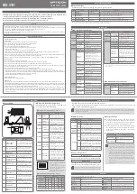
Fig. 2-204 is a sectional diagram of the
reading unit. The reading unit consists of the
sensor drive PCB, image sensor PCB, lens array,
LEDs (R/G/B), light guide, and reading glass.
The contact image sensors (CIS) are mounted
on the image sensor PCB in a single row, with a
density of 600 dpi. The valid reading width is 305
mm, and the number of valid pixels is 7260. The
optical resolution can be switched between 600 dpi
and 300 dpi by an external signal.
The main feature of this reading unit is that it
provides lighting for the image sensors using two
LEDs, lighting the document from both the right
and left sides as shown in the figure. The light
guides are arranged on the right and left side, and
a red (R), green (G), and blue (B) LED is arranged
for each light guide on the image sensor PCB.
LEDs light illuminate the document through
the light guides, and the light reflected from the
document enters the image sensors through the
lens array. The image sensors convert the light to
an analog signal. The analog signal is sent to the
sensor drive PCB, and then to the main CPU PCB
as a digital signal after A/D conversion and
shading correction.
In the binary or grayscale mode, the image is
read with composite light generated by lighting all
the RGB LEDs simultaneously. In the color mode,
the RGB LEDs are sequentially lit, and the image
data is read separately for each color. In the
drop-out color mode, only the LEDs of the
designated color are lit.
In the previous models (DR-5020/5080C), A/D
conversion and shading correction were handled
by the image processor on the main CPU PCB, but
in this model they are processed internally by the
reading unit.
Reading glass
Sensor drive PCB
Image sensor
PCB
Image sensor (CIS)
Light guide
Light guide
Lens array
LEDs (R/G/B)
LEDs (R/G/B)
Document
Fig. 2-204
Summary of Contents for ImageFormula DR-9080C
Page 4: ......
Page 22: ......
Page 182: ......
Page 188: ...1003N0 0 1...
Page 195: ...COPYRIGHT 2003 CANON ELECTRONICS INC CANON DR 6080 9080C FIRST EDITION OCT 2003 vii...
Page 236: ......
Page 240: ......
Page 242: ...ix 1003N0 0 0...
Page 284: ...38 Chapter 3 Software Closing CapturePerfect 1 Select Exit from the File menu...
Page 308: ......
Page 352: ...1 Imprinter for DR 6080 9080C Installation Procedure IMS Product Planning Dept...
Page 355: ...4 3 Remove the left cover 4 screws Remove these screws x4...
Page 359: ...8 7 Insert it firmly to the back and fix it with 1 screw M3x6...
Page 366: ...15 14 Replace the cable to cable clamp and the document eject cover to the original position...