5 - 12
COPYRIGHT © 2003 CANON ELECTRONICS INC. CANON DR-6080/9080C FIRST EDITION OCT. 2003
CHAPTER 5 TROUBLESHOOTING
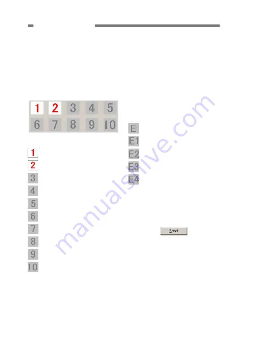
b) Sensors of the main body
When a sensor on the main body is in a state
of detection, the mark corresponding to the
sensor will illuminate. Fig. 5-308 shows the
case in which the document tray HP sensor
and the document sensor is are in a state of
detection. The mark ‘1’, which corresponds to
the document tray HP sensor, will illuminate if
the document tray is lowered, and will turn off
when it starts to rise.
Fig. 5-308
Document tray HP sensor
Document sensor
Upper unit opening/closing sensor
Pick-up sensor (Refer to Note)
Imprinter door sensor
Left-end sensor
Front registration L sensor
Back registration sensor
Front registration R sensor
Right-end sensor
Note:
When something is wrong with the
operation of the pick-up sensor, the sensor
position is thought to be incorrect. This
problem occurs quite often, especially
when disassembling or reassembling the
pick-up sensor. For the adjustment, refer
to the “VIII. AFTER REPLACING PARTS”.
c) Endorser
As with the sensors on the main body, when
the endorser button LED is pressed, or the
sensor of the endorser is in a state of
detection, the mark corresponding to the
sensor will illuminate.
Endorser button LED
Die drum HP sensor
Document sensor
Cover open sensor
Die drum open sensor
d) Operation panel LEDs
The ‘Panel’ button is shown in Fig. 5-309. If
this button is selected, the operation panel
LEDs alternate illuminating normally,
illuminating all, and turning off all.
Fig. 5-309
Summary of Contents for DR-6080
Page 4: ......
Page 22: ......
Page 182: ......
Page 188: ...1003N0 0 1 ...
Page 195: ...COPYRIGHT 2003 CANON ELECTRONICS INC CANON DR 6080 9080C FIRST EDITION OCT 2003 vii ...
Page 236: ......
Page 240: ......
Page 242: ...ix 1003N0 0 0 ...
Page 284: ...38 Chapter 3 Software Closing CapturePerfect 1 Select Exit from the File menu ...
Page 308: ......
Page 352: ...1 Imprinter for DR 6080 9080C Installation Procedure IMS Product Planning Dept ...
Page 355: ...4 3 Remove the left cover 4 screws Remove these screws x4 ...
Page 359: ...8 7 Insert it firmly to the back and fix it with 1 screw M3x6 ...
Page 366: ...15 14 Replace the cable to cable clamp and the document eject cover to the original position ...


