background image

step

Action

additional Info

3

Service screen

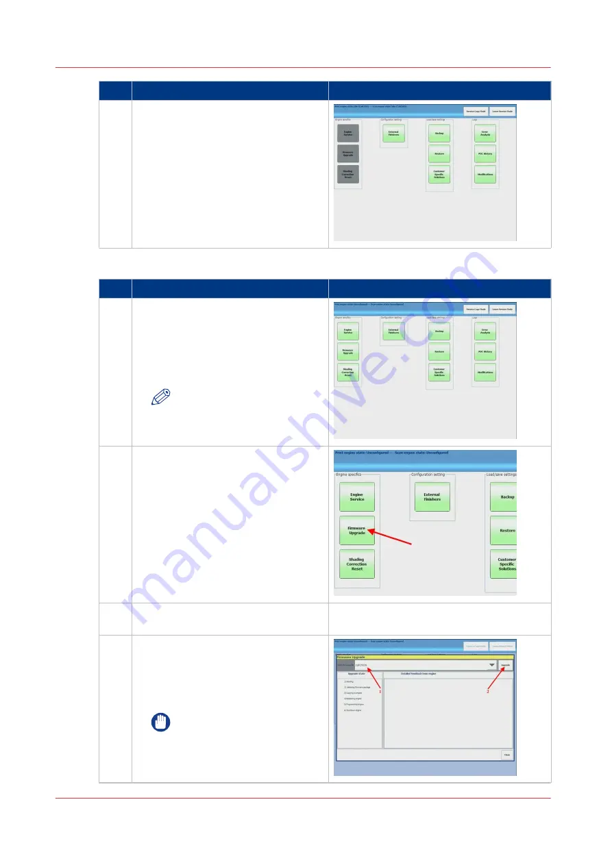
Wait until the 'Service Screen' is dis-
played.
The 3 blocks on the left are greyed-out,
meaning there is no connection with the
printer.

Start upgrade procedure

step

Action

additional Info

1

Switch on the printer

Switch on the engine with the power-
switch. When the connection between
the printer and the PRISMAsync is es-
tablished, the 3 blocks will become
green.

NOTE

Be sure to switch on the print-
er within 2 minutes after
switching on the PRISMAsync.

2

Firmware upgrade

Select [Firmware Upgrade].

3

Insert USB key with printer and options
firmware in the PRISMAsync


4

Firmware upgrade

1. Select the correct firmware to install

(iPC7010S)

2. Press 'Upgrade' to start the upgrade

process.

IMPORTANT

Do not switch off the PRISMA-
sync and the printer during the
installation process.

4

Firmware upgrade of Engine and Accessories (safe download mode)

88

Chapter 8 - Firmware upgrades via PRISMAsync

PRISMAsync V3.2

Summary of Contents for Digital Video Software v.32

Page 1: ...cal Service Manual PRISMAsync v3 2 for imagePRESS C7010VPS Series C7011VPS Series COPYRIGHT 2015 CANON Inc CANON PRISMAsync v3 2 for imagePRESS C7010VPS Series C7011VPS Series PRINTED IN U S A January 5 2015 ...

Page 2: ...Edition 2014 12 GB ...

Page 3: ...em settings 28 Maintenance and Service 31 System service mode PRISMAsync service mode 35 Engine service mode during printing 38 Colour adjustments 41 Media management 45 Operator maintenance 47 Chapter 5 Start shutdown and restart the system 49 Turn on the system 50 Turn off the system 51 Restart the system 52 Restart the copier only 53 Restart copier after error in copier 55 Chapter 6 The Setting...

Page 4: ... Troubleshooting 109 Troubleshooting 110 Check external connections 111 Checking internal components 112 Comprehensive system inspection 113 Diagnose LEDs 115 Error messages and conditions 118 11504 Error Screen behaviour 122 Handling of 11504 MRE 125 Beep codes PRISMAsync 126 Chapter 11 Appendix 129 Appendix A Specifications 130 Hardware features 130 Connectivity 131 Appendix B Parts overview 132...

Page 5: ... reports 153 Appendix F The Trapping editor 158 The Trapping editor 158 Appendix G EAC document 161 EAC model number overview 161 Appendix H System overview 162 System overview 162 Contents 5 PRISMAsync V3 2 ...

Page 6: ...Contents 6 PRISMAsync V3 2 ...

Page 7: ...Chapter 1 Preface ...

Page 8: ...es not apply to any countries where such provisions are inconsistent with local law Trademarks The product names and company names used in this manual are the registered trademarks of the individual companies Copyright This manual is copyrighted with all rights reserved Under the copyright laws this manual may not be copied reproduced or translated into another language in whole or in part without...

Page 9: ...SION IF BATTERY IS REPLACED BY AN INCORRECT TYPE DISPOSE OF USED BATTERIES ACCORDING TO THE INSTRUCTIONS CAUTION WENN MIT DEM FALSCHEN TYP AUSGEWECHSELT BESTEHT EXPLOSIONSGEFAHR GEBRAUCHTE BATTERIEN GEMASS DER ANLEITUNG BESEITIGEN Preface Chapter 1 Preface 9 PRISMAsync V3 2 ...

Page 10: ...Preface 10 Chapter 1 Preface PRISMAsync V3 2 ...

Page 11: ...Chapter 2 Introduction ...

Page 12: ... by using a detailed media catalogue High speed colour calibration allowing you to calibrate for all media and halftone screening in one go Basic or professional colour management depending on access rights of users Simple colour presets for inexperienced operators and users Automated workflows allowing users to define their own templates Last minute colour correction buttons to apply last minute ...

Page 13: ...Chapter 3 Installation ...

Page 14: ...tenance is lost In that case a service technician has to reset the password NOTE The Remote Manager password is called Operator password in the Settings Editor Do the following steps to reset the passwords Procedure 1 Open the Settings Editor on a remote PC connected to the network of the customer See The Settings editor on page 58 2 Browse to Configuration Security and select Reset the system adm...

Page 15: ...eed to move the copier away from the wall so that interface connectors are accessible Check if the interface cables between copier and PRISMAsync are present 1 data cable must be delivered together with the copier 1 Ethernet cross cable is delivered with the PRISMAsync Power Network Is a dedicated grounded electrical outlet for the PRISMAsync available near the copier Locate the grounded electrica...

Page 16: ...SMAsync to the engine it is necessary to assemble the Operator panel For the assembly instructions refer to the imagePRESS C7010VPS C7011VPS engine service manual chapter 2 installation Assemble the Operator panel 16 Chapter 3 Installation PRISMAsync V3 2 ...

Page 17: ...x Store the original box and packing material in case the PRISMAsync needs to be transported at a later date 2 Check the contents of the box 3 Provide the customer with the Safety Notice and User Documentation and Printer Driver Notice The user documentation can also be downloaded from http downloads oce com NOTE Also see the engine service manual Unpack the PRISMAsync Chapter 3 Installation 17 PR...

Page 18: ...o be replaced with the supplied pedestals Replacement of the installed supports 1 Remove the 4 supports installed on the PRISMAsync controller The removed supports and screws will not be used 4x 2 Install the supports delivered with the PRISMAsync controller 4x M3x16 Hex bolt 4x Install the PRISMAsync supports pedestals 18 Chapter 3 Installation PRISMAsync V3 2 ...

Page 19: ...rator panel Connect the other side to the left DVI port on the backside of the PRISMAsync 4 Connect the 15 pins D sub connector to the connector on the backside of the PRISMA sync Connect the other side to the backside of the operator panel 5 Connect a USB cable to the backside of the operator panel Connect the other side to the backside of the PRISMAsync 6 Close the backside of the operator panel...

Page 20: ...so may permanently damage the port or the cable Connect the Operator Attention Light Step Action 1 Install the Operator Attention Light to the backside of the copier 2 Connect the cable with the 9 pins D sub connector to the connector on the backside of the PRISMAsync 3 Connect the other side of the cable to the connector attached to the Attention Light Connect to the network Step Action 1 Connect...

Page 21: ...all data cables to the PRISMAsync The power cord is not fixed with the tie wrap Step Action Remark 1 Bundle all data cables and guide them in the same direction NOTE Do not bundle the power cable with the data cables 2 Guide the bundle in a loop going upwards and then downwards NOTE Make sure there is not too much tension on the connectors 4 Connect the PRISMAsync Chapter 3 Installation 21 PRISMAs...

Page 22: ...ide of the controller as shown and lead the bundle in a curve along the rear side of the controller downwards NOTE Fasten the tie wrap without drawing the cables too tight The tie wrap can be released and reused Connect the PRISMAsync 22 Chapter 3 Installation PRISMAsync V3 2 ...

Page 23: ...he settings On the panel touch System Setup Local key operator settings Touch the button of the group that contains the setting you want to change e g Connectivity for network settings Touch the required setting and enter the desired value Touch OK 7 If the PRISMAsync came with no licenses please install them now Refer to Installing a license on page 105 8 Perform any required system software upgr...

Page 24: ...the customer with the installation of the printer driver on 1 workstation The printer driver can be found by using the Settings Editor On your PC open an Internet browser e g Microsoft Explorer In the Address bar enter http hostname or IP address A window with the Settings Editor will open Go to the Support tab Touch Software At the bottom of the page you will find the drivers which can be downloa...

Page 25: ...Chapter 4 Using the PRISMAsync ...

Page 26: ...n the printer and the controller Startup the controller after a shutdown 2 Stop button Stop the printer After a set or As soon as possible 3 Paper tray button Get direct access to the tray section on the operator panel to do the following Check the content of all paper trays Load a new media type into a paper tray Change the media type which is available in one of the paper trays Create a trace lo...

Page 27: ...ce Set up the preferred work flows Change a number of default system settings Adjust the brightness and contrast of the LCD panel Shut down the printer View the content of the Media catalogue or add temporary media to the Media catalogue 9 Dashboard The dashboard displays information about the system status such as Information about the current printing process Information about operator intervent...

Page 28: ...on light Job name truncation Define the way the System shortens the job name when the job name is too long to display fully Operator panel settings Adjust the brightness and contrast of the screen of the operator panel Shut down system Shut down the printer and the controller in a controlled way The advanced section displays the following button Intermediate Check Print Press the button to force a...

Page 29: ...cense to activate a new feature on the printer you can upload the license file through this section After uploading the license file the feature becomes active 3 Logging Save the datadump file When an error occurs you can create a datadump file The datadump file is a zip file that contains detailed technical information about the System Save the trace file The System can also store trace log files...

Page 30: ...ed IPv6 TCP IP address IPv6 link local address IPv6 prefix length IPv6 gateway IPv6 DNS 1 IPv6 DNS 2 5 System settings Date and time System of measurement Time zone System settings 30 Chapter 4 Using the PRISMAsync PRISMAsync V3 2 ...

Page 31: ...ervice Mode it is possible to select which counters to display and additional toner bottle counters can be added Maintenance mode When you push the Start maintenance button you will enter a mode in which you can perform some adjustments to the system All the adjustments are guided by a wizard to make your job easier A password is required to enter the maintenance mode default 12345 1 Stacker Repla...

Page 32: ...hes of uneven gloss may appear in the high density areas of the printed heavy paper or coated paper In this case the lines and patches of uneven gloss may be reduced by refreshing the fixing roller and cleaning its surface System service and engine service mode To enter service mode via the maintenance screen 1 Select the Go to the service mode button 2 Enter the PIN 675756 3 The following screen ...

Page 33: ...lyse and execute settings ad justments via system SDS To analyse the engine when in an error situation How to access Description User Interface After an error occurred Select Go to service mode on error screen Engine state Off Status bar Off Level low Purpose To analyse the PRISMAsync in an error situation Engine state On with error Status bar Off Level low Purpose To analyse the engine and PRIS M...

Page 34: ...ystem Serv ice or Engine Service Engine state On Status bar Ready Level Standby Purpose For all situations described above and maintenance checks NOTE The Engine Service mode during printing is only accessible via the Maintenance tab in normal user mode Maintenance and Service 34 Chapter 4 Using the PRISMAsync PRISMAsync V3 2 ...

Page 35: ...ISMAsync controller The SDS is used by the FST to configure diagnose backup and restore settings for the print engine accessories and PRISMAsync controller System service mode PRISMAsync service mode 2 Service Diagnostic System 1 Service Copy Mode System service mode PRISMAsync service mode Chapter 4 Using the PRISMAsync 35 PRISMAsync V3 2 ...

Page 36: ...nt engine service mode All service functionality is available NOTE The Updater button is not supported in this screen and therefor the result is unpredictable The function of the other buttons is described in the service manual of the engine 4 Firmware Upgrade With this button you can start the upgrade procedure of the firmware of the copier A USB stick containing the firmware should be available ...

Page 37: ...em will ask for a filename After selecting the correct file the settings are restored to the PRISMAsync When restoring is ready the PRISMAsync will reboot automatically 9 Customer Specific Solutions For some customers it is possible that specific solutions for their system are made In this screen you can disable or enable these solutions 10 POC Configuration In the POC configuration screen you can...

Page 38: ...de during printing is only accessible via the Maintenance tab in normal user mode Engine Service mode NOTE The illustrations below should be used as a reference and might differ from the actual content displayed on the user interface The engine service mode is for monitoring and analysis only This mode can be used during printing 1 Select Engine Service to enter the engine service mode during a pr...

Page 39: ... service mode select Switch to normal UI to switch to normal user interface 3 From the normal user interface select Go to the service mode to switch back to engine service during printing 4 The coloured bar on the Dashboard in the normal user interface indicates the engine service mode during printing is still active Engine service mode during printing Chapter 4 Using the PRISMAsync 39 PRISMAsync ...

Page 40: ...5 To leave the engine service mode and return to the normal user mode select Leave Service Mode Engine service mode during printing 40 Chapter 4 Using the PRISMAsync PRISMAsync V3 2 ...

Page 41: ... is used to scan and to correct the irregularities automatically In this part you can choose between 1 Full adjustment This option does the auto gradation adjustment by printing sheets and measuring them either automatically or via the glass platen 2 Quick adjustment The measurement is done without printing any paper but is considered to be less accurate than the Full adjustment We advise not to u...

Page 42: ... timer for normal media When the auto gradation adjustment timer is enabled the system automatically requests an auto gradation adjustment at the beginning of the last day of the time interval Set the time interval to zero days to disable the auto gradation adjustment timer Default 1 Day Auto gradation adjustment timer for heavy media When the auto gradation adjustment timer is enabled the system ...

Page 43: ...he gradation density and colour settings of the printer The measurement is done without printing any paper but is considered to be less accurate than the Full adjustment We advise not to use this adjustment Reset engine calibration curves It is possible to reset the actual calibration shading curves In the dialogue you have to select the curve to delete After deletion you have to perform the calib...

Page 44: ...olour configuration report selectable for information bar 7 Factory default trapping disabled 7 Trapping Preset Editor NOTE See the appendix for a description of the trapping presets Colour adjustments 44 Chapter 4 Using the PRISMAsync PRISMAsync V3 2 ...

Page 45: ...1 Skew and right angle correction Select a specific media that you want to adjust Select the Skew Correction adjustment A wizard will start guiding you through the adjustment 9 Skew correction 2 Curl correction Select a specific media that you want to adjust Select the Curl correction adjustment A screen will pop up in which you can enter the values Descriptive images tell you if these values need...

Page 46: ...adjust Select the Registration correction adjustment 11 Registration correction Result 1 Repeat the procedures for each paper type you want to adjust 2 The calculated values can be checked in the Settings Editor Media management 46 Chapter 4 Using the PRISMAsync PRISMAsync V3 2 ...

Page 47: ...intenance button in the Maintenance Mode section Follow the steps below to use the Operator Maintenance Application Procedure 1 Select Engine Maintenance out of the options The following windows is displayed Fig Operator maintenance screen 1 2 Click Next After a few seconds the following screen is displayed Fig Operator maintenance screen 2 3 It is now save to start the omapp from a remote PC Open...

Page 48: ...Operator maintenance 48 Chapter 4 Using the PRISMAsync PRISMAsync V3 2 ...

Page 49: ...Chapter 5 Start shutdown and restart the system ...

Page 50: ...ion 3 If required wait until the controller is ready 4 Press the Sleep button Moon at the right hand side of the operator panel If the controller was switched off completely press the on off button on the controller NOTE The controller needs some time to start up In the beginning the screen will be black Please be patient until the splash screen is displayed NOTE In some cases the system needs to ...

Page 51: ... Touch System Setup Shut down system The operator panel displays the message Are you sure you want to shut down 2 Touch Yes A message indicates when the shut down will begin The shut down can take a maximum of 60 minutes NOTE Using the Shut down now option can damage the printer Use the Shut down now option only to turn the printer off and on within 10 minutes 3 Turn off the optional equipment Tur...

Page 52: ... PC 2 Go to Support Troubleshooting 3 Select Restart the system To restart the system via the operator panel 1 Touch System Setup Shut down system The operator panel displays the message Are you sure you want to shut down 2 Touch Restart NOTE In some cases the system needs to reboot the engine max 2x to reach the correct start up situation Restart the system 52 Chapter 5 Start shutdown and restart...

Page 53: ...r code 11506 is shown and the message Press moonbutton to continue is displayed 2 Press the Sleep button After this the error will be reset If you do not press this button and you will switch to normal user mode the error screen will be displayed 3 The Service screen will not function now because the copier is off You might get the following screen 13 Service Screen when copier is off 4 Switch on ...

Page 54: ...ress the Sleep button to reset the error 5 From this point on you have the same situation as previously described Restart copier in Service Mode NOTE In some cases the system needs to reboot the engine max 2x to reach the correct start up situation Restart the copier only 54 Chapter 5 Start shutdown and restart the system PRISMAsync V3 2 ...

Page 55: ...1 Switch all finishers and paper modules off 2 Check if power cords are plugged in 3 Wait at least 3 seconds 4 Switch all finishers and paper modules on 5 Press the Sleep button to restart the printer NOTE The copier will restart without restarting the PRISMAsync NOTE In some cases the system needs to reboot the engine max 2x to reach the correct start up situation Restart copier after error in co...

Page 56: ...Restart copier after error in copier 56 Chapter 5 Start shutdown and restart the system PRISMAsync V3 2 ...

Page 57: ...Chapter 6 The Settings Editor ...

Page 58: ... the PC and the PRISMAsync are connected to the client network On the PC open an Internet browser eg Microsoft Explorer In the address bar enter the IP address or the Hostname of the PRISMAsync As a result the Settings Editor will open It is now possible to make changes in the above listed areas Access via direct connection to PRISMAsync Sometimes you can not access the Settings Editor via the cli...

Page 59: ... 16 Fig Settings Editor NOTE See the Settings Editor user manual for important printer adjustments for media The Settings editor Chapter 6 The Settings Editor 59 PRISMAsync V3 2 ...

Page 60: ...The Settings editor 60 Chapter 6 The Settings Editor PRISMAsync V3 2 ...

Page 61: ...Chapter 7 Service procedures ...

Page 62: ...nger supported o No DVD player o There are 2 different sub versions of this controller in the field These have different GPU boards installed Version 3 with N550GTX TI GPU 1070006840 Version 3 with GTX650 GPU 1070026100 The N550GTX GPU will not be delivered anymore Version 4 hardware This version is also known as A4 Differences with the previous versions o More RAM memory This version has four mem...

Page 63: ...utomatic loading of DDI firmware depending on XPe or W7 platform Old PBA AUX board from version 2 controller 1060111070 is not compatible with version 3 or higher controller hardware If you have to exchange the Base controller from a version 2 controller hardware with a higher version you also need a new PBA AUX control board A new PBA AUX control board 1070005457 can be used in a version 2 contro...

Page 64: ... V3 INDUSTRIAL CON TROLLER GPU 1060131773 inclu ded n a n a n a n a v v 1 1070026100 VHE CTRL MB950 V3 INDUSTRIAL CON TROLLER GPU 1070026086 inclu ded n a n a n a n a V2 2 v 1 1070033079 VHE CTRL MB950 V4 INDUSTRIAL CON TROLLER n a n a n a n a n a v 1060120116 MEMORY MODULE 2GB DDR3 v v v v v n a 1070037688 4GB DDR3 DIMM SPARE PART n a n a n a n a n a v 1070026086 GPU SPARE PART V2 2 V2 2 V2 2 v 1...

Page 65: ... v 1060118980 SIGNAL LAMP ASSY v v v v v v V2 2 SW Version V2 x or higher is mandatory for hardware configuration sup port v 1 see release notes for performance limitation of specific features Not Supported Controller compatibility Chapter 7 Service procedures 65 PRISMAsync V3 2 ...

Page 66: ...ooler 2 On Off switch 13 CMD connection copier 3 Not used 14 Graphics board GPU 4 Network connection 15 DDI Interface board 5 USB ports 16 AUX control board 6 Not Used 17 Attention light connection 7 UI panel DVI 18 Hard Disk Drives 250GB 8 Data connections copier 19 DIMMs 9 UI panel 20 System fan 10 Power supply 21 Network card IPDS 11 Motherboard NOTE See the Hardware components overview 66 Chap...

Page 67: ...back of the PRISMAsync controller If you have wrapped the cables then release the tie wrap 3 Remove the left side cover of the PRISMAsync controller To remove the side cover remove the 3 screws at the right side on the back of the PRISMAsync controller Then shift the cover to the back to let it come off 4 Open the cable ties attached to the middle bracket These ties are re usable and are meant for...

Page 68: ... PRISMAsync 4 Firmly press the PCI E lock mechanism to unlock the board The lock mechanism is located at the bottom right side of the PCI E connector on the motherboard Pressing it down will lift the board out of the connector 5 Remove the board from the PRISMAsync 6 Install the new board in the PCI E connector Firmly press the board in the PCI E 1 connector the upper Check that the lock mechanism...

Page 69: ...k if the old GPU board is the same as the new one If not it could be necessary to reinstall system software needs to be re installed because of a new driver that is needed for this GPU Replace the GPU board Chapter 7 Service procedures 69 PRISMAsync V3 2 ...

Page 70: ...bracket Use a small Philips screwdriver to remove the screw used to mount the bracket to the backside of the PRISMAsync 4 Remove the PCI card from it s slot Hold the PCI card by the two top corners Pull it straight out of the socket 5 Take the board out of the PRISMAsync 6 Unpack the new board 7 Place the board in the PCI E connector Firmly press the board in the PCI E connector Use the PCI E 3 po...

Page 71: ...de of the PRISMAsync 4 Remove the PCI card from it s slot Hold the PCI card by the two top corners Pull it straight out of the socket 5 Remove the board from the PRISMAsync 6 Unpack the new board 7 Connect the USB wire connector The USB wire connector white side must be connected to the Auxiliary Board Be cause of the space between Board and controller box it s advised to do this before inserting ...

Page 72: ...driver 10 Connect the internal connectors to the board See Access internal components on page 67 11 Re install middle bracket and side cover Make sure the fixing on the middle bracket is in position It should fit exactly on the AUX control board Replace the AUX control board 72 Chapter 7 Service procedures PRISMAsync V3 2 ...

Page 73: ...as described in Access internal components on page 67 2 Open the clips by pressing them outward Firmly press on the clips on the left and the right side of the connector The DDR3 module will be lifted out of the connector 3 Align the DDR3 module with memory slot 4 Install the DDR3 module in memory slot Gently push the DDR3 module in an upright position until the clips of the slot close to hold the...

Page 74: ...ys exchange all 3 drives at once The 2 data drives are Raid0 configured This means that if 1 disk has crashed all the data will be lost Step Action 1 Remove side cover Follow the instructions as described in Access internal components on page 67 2 Disconnect the connectors Unplug the power and the SATA connectors on the HDD 3 Remove the 2 screws on the front side 4 Slide the HDD outward 5 Insert t...

Page 75: ...he new board 3 Remove the fifth metal bracket starting from the CPU Use a Philips screwdriver to remove the bracket 4 Place the board in the PCI connector Firmly press the board in the PCI connector NOTE Make sure to use the indicated slot 5 Fasten the Ethernet board Fasten the board with a single screw on the PCI bracket side with a Philips screw driver 6 Re install middle bracket and side cover ...

Page 76: ...rd on page 75 Optional HDDs See Replace the Hard Disk Drives on page 74 If HDDs are still working you can exchange the hard disks In this case all set tings and jobs will be saved and no new system software installation is nee ded 3 Remove harness 22W01 4 Remove the connections at the backside of the PRISMAsync 5 Unpack the base controller 6 Remove side cover and middle bracket Follow the instruct...

Page 77: ...nn the defect controller See also Hard Disk Drives 13 Install system software In case that the hard disks were not exchanged you have to install the latest PRIS MAsync software 14 Restore a backup If you have a backup of the system before it crashed you can restore it now All set tings will be restored except the licenses because they belong to the old control ler 15 Re host and install licenses S...

Page 78: ...ap around your wrist to avoid electrostatic discharge that will harm your equipment Illustration 23 Harness 22W01 Step Action 1 Be sure the AUX control board is mounted correctly in the PRISMAsync 24 Connected AUX control board 4 Connect Harness 22W01 78 Chapter 7 Service procedures PRISMAsync V3 2 ...

Page 79: ...harness to AUX board 1 Connect harness 22W1 to the AUX board 2 Connect standby power supply connector to the AUX board 3 Disconnect the On Off motherboard cable 26 Disconnect On Off Motherboard cable 4 Connect Harness 22W01 Chapter 7 Service procedures 79 PRISMAsync V3 2 ...

Page 80: ...ectors 27 Connect harness to On Off connectors 5 Fasten the harness Fasten the harness 22W01 with the bundle holder Make sure no cables or connec tors can touch the fan 28 Fasten harness Connect Harness 22W01 80 Chapter 7 Service procedures PRISMAsync V3 2 ...

Page 81: ...Chapter 8 Firmware upgrades via PRISMAsync ...

Page 82: ...on Firmware USB installation key by using the SST Tool Print the PRISMAsync configuration report colour configuration report and the printer P_PRINT Service Mode Firmware upgrade of engine and accessories from USB NOTE Please follow the steps in the exact order as described below Any changes in the order might give unpredictable results Enter Service Mode step Action additional Info 1 NOTE Make su...

Page 83: ... correct firmware to install iPC7010S 2 Press Upgrade to start the upgrade process IMPORTANT Do not switch off the PRISMA sync and the printer during the installation process 4 Firmware upgrade validation As a first step a validation of the firm ware will take place 4 Firmware upgrade of Engine and Accessories Chapter 8 Firmware upgrades via PRISMAsync 83 PRISMAsync V3 2 ...

Page 84: ... instal lation will continue without any problems 10 Switch off and on the printer When the process is completed a screen is displayed prompting you to switch the printer off and on again Take the following steps 1 Restart the printer Switch off the printer with the power switch Switch off all accessories finish ing paper decks etc Switch on all accessories Switch on the printer with the power swi...

Page 85: ...figuration report PRISMAsync color configuration re port Printer P Print Compare the configuration report and the P Print with the version list as stated in the serv ice bulletin and release notes NOTE Explicitly check the SORTER ver sion If the version does not corre spond make a USB key with the SORTER package only and do an in stallation again There is no need to go to Safe Download Mode now Ex...

Page 86: ... update is done in Safe Download Mode to guaranty the data transfer between PRISMAsync controller and the print engine Please follow the steps in the exact order as described below Any changes in the order might give unpredictable results Set up the system to enable upgrade step Action additional Info 1 Shutdown system Shut down the system with the Sleep button Select Shutdown and then Shutdown Th...

Page 87: ...the Sleep button NOTE Do NOT switch on the printer Enter Service Mode step Action additional Info 1 Go to service mode When the splash screen is shown press the go to service mode button 2 Logon to service mode In the next screen enter the Service Password 4 Firmware upgrade of Engine and Accessories safe download mode Chapter 8 Firmware upgrades via PRISMAsync 87 PRISMAsync V3 2 ...

Page 88: ...hed the 3 blocks will become green NOTE Be sure to switch on the print er within 2 minutes after switching on the PRISMAsync 2 Firmware upgrade Select Firmware Upgrade 3 Insert USB key with printer and options firmware in the PRISMAsync 4 Firmware upgrade 1 Select the correct firmware to install iPC7010S 2 Press Upgrade to start the upgrade process IMPORTANT Do not switch off the PRISMA sync and t...

Page 89: ...re is cop ied to the printer 7 Normal download mode As soon as all the software is copied a screen is displayed telling you to reset the DIP switch 8 Switch to Normal download mode On the backside of the printer Set the DIP switch SW1 to OFF Lower posi tion 4 Firmware upgrade of Engine and Accessories safe download mode Chapter 8 Firmware upgrades via PRISMAsync 89 PRISMAsync V3 2 ...

Page 90: ...e following steps 1 Restart the printer Switch off the printer with the power switch Switch off all accessories finish ing paper decks etc Switch on all accessories Switch on the printer with the power switch 2 Select OK 11 Leave firmware upgrade mode Press Close to leave the firmware Up grade mode 12 Remove USB key with Printer firmware The duration of the printer upgrade procedure depends on the...

Page 91: ...d release notes NOTE Explicitly check the SORTER ver sion If the version does not corre spond make a USB key with the SORTER package only and do an in stallation again There is no need to go to Safe Download Mode now Example Additional information For additional information see Firmware upgrade additional information on page 92 Firmware upgrade of Engine and Accessories safe download mode Chapter ...

Page 92: ...sync will check if the installed engine and accessories firmware level matches with the actual installed PRISMAsync version Version checking is executed when starting a connection with the engine in normal user mode In safe download mode version checking is not executed If non matching firmware is found PRISMAsync will report this in the data log The data log information can be viewed in service m...

Page 93: ...s set to safe download mode Pop up menu is requesting to shut down en gine and accessories and switch on engine and accessories again This pop up screen is indicating that a fault is occurred Most likely the firmware of one of the accesso ries is not installed correctly Check for reason and take corrective actions Action required Power off and on the engine NOTE For imagePRESS C800 series the ac c...

Page 94: ...esent The scroll bar can be used to review the infor mation to find the applicable module Check for reason and take corrective actions Fault detected with USB key File name or content is invalid For analysis the current upgrade policy can be checked via PRISMAsync service mode Er ror analyses The current policy is showed Af ter each PRISMAsync the policy is checked again NOTE Only applicable for P...

Page 95: ...Chapter 9 System software ...

Page 96: ...ion To check the software version 1 Open the Settings Editor and browse to Support About In the field Version of the printer main software the version is given 2 In the System section of the setup tab on the Operator panel touch Local key operator settings In the section About you will find the version number In some cases it is necessary to re install the system software A newer version of the so...

Page 97: ...k 2 Insert USB key and start CreateUSB Tool 1 Fill out the fields in the tool Once the iso file is selected the tool will check if a newer version is available in the image file If there is a new version available it will install this version and overwrites the old one The following dialogue will appear 3 Restart the Create USB Tool Restart the tool and make the settings as described below 1 Insta...

Page 98: ... window will pop up Select Yes to store existing jobs and settings and to restore them automatically after the installation NOTE The keep existing jobs and settings after installation setting is supported in version 3 2 and higher After making the selection the process will start and the iso image is programmed to the stick Please wait until the CreateUSB tool indicates that the USB stick is eject...

Page 99: ...Check if the name of the USB stick is USEDKEY 4 To prepare the USB stick for reuse open the contents of the stick in your explorer Double click the ReUseKey bat file 5 Check in your explorer screen if the name of the USB stick has changed to OCEINSTALL If the name did not change it might be needed that you remove the stick and insert it again 6 Your USB stick is now ready for a new installation NO...

Page 100: ...the Maintenance tab on the Operator panel touch Go to service mode 3 In the first screen touch the Backup button The system will detect the USB stick and will ask to confirm the location and filename After confirmation the settings are copied to the USB stick 4 Remove the USB stick after the settings are copied 3 Insert the USB stick that contains the system software into a USB port Be sure to ins...

Page 101: ...ervice mode See also Service mode in Maintenance and Service on page 31 3 In the first screen touch the Restore button The system will detect the USB stick and will ask to confirm the location and filename After confirmation the settings are copied to the PRISMAsync 4 When all the settings are copied the PRISMAsync will automatically reboot When ready please remove the USB stick If you were not ab...

Page 102: ...mote Service needed Install a patch from a PC via the Settings Editor To install a patch from a PC via the Settings Editor take the following steps 1 Be sure the patch is installed on your PC laptop 2 Browse to the software upgrade section In your web browser open the Settings Editor and browse to Support Software Select the Upload upgrade package 1 option Depending on the new software version som...

Page 103: ... next window choose About Upgrade software from USB The system will ask you for the location of the USB stick and the filename 3 Select the patch file In the next window browse to the location were the EXE file with the patch resides Select the file and select Upgrade on the Operator Panel 4 Wait until the installation finishes When the installation has finished the message Installation successful...

Page 104: ...b choose Local key operator settings 2 Install Windows upgrade or uninstall Windows upgrade 3 Select the patch file In the next window browse to the location were the MSU file with the patch resides Select the file and select Install on the Operator Panel 4 Wait until the installation finishes When the installation has finished the message Installation successful is shown 5 Restart the PRISMAsync ...

Page 105: ...key operator settings In the next window choose Software licenses upload license The System will ask you for the location of the USB stick and the filename Choose the correct file and touch Start When the file is uploaded restart the PRISMAsync Make a backup of the settings 2 In the Settings Editor Locate the license file on your PC On your PC open the Settings Editor SeeThe Settings editor on pag...

Page 106: ... to obtain the printer driver via the Settings Editor Open a web browser and browse to your system Go to the tab Support Software Here you will find an item to download the printer driver You will need the Key operator PIN or System Administrator password for this After entering the PIN a window will pop up asking you to select the appropriate driver Click on the needed item The driver will be dow...

Page 107: ... Colour Colour presets Photographic content Device CMYK input profile US Web Coated SWOP Media select edit Media family depending region All Uncoated Media Use Uncoated media family for uncoated media in the EU Use Uncoated US media family for uncoated media in the US Use Uncoated JP media family for uncoated media in Japan For transaction printing US set media and Colour Management IPDS 36 media ...

Page 108: ... weights Media weights up to 161 78 grams square meter must be entered in Bond and media with a higher media weight must be entered as index Configure the machine for the USA 108 Chapter 9 System software PRISMAsync V3 2 ...

Page 109: ...Chapter 10 Troubleshooting ...

Page 110: ...the checks you can perform to locate and resolve problems Always check the external and internal before replacing any components NOTE If an error code is displayed on the operator panel please check the list with error codes in Error messages and conditions on page 118 Check that the network of the customer is functioning If this is not the case direct these problems to the appropriate service dep...

Page 111: ...over Ethernet cable and normal Ethernet cable upper network port are not exchanged 6 Both data cables are connected correctly to PRISMAsync and copier 7 USB cable to operator panel is connected 8 DVI cable to operator panel is properly connected Left DVI port 9 15 pin D sub cable to operator panel is connected 10 9 pin D sub cable to Operator attention light is connected 11 Cables in the backside ...

Page 112: ...dling electronic components Check the following Procedure 1 No strange objects are inside the PRISMAsync 2 Look for obvious loose boards Reseat each board including DDR3 modules 3 Look for obvious loose connectors Reseat each connector firmly 4 Be sure that HDDs are connected to the right SATA port See Replace the Hard Disk Drives on page 74 Checking internal components 112 Chapter 10 Troubleshoot...

Page 113: ...y foreign objects Motherboard Motherboard including components and traces appear undamaged and no foreign objects are evident CPU is present well seated and appears undamaged CPU cooling assembly is well aligned and firmly attached Each fan including fan cable is well positioned not upside down installed in the correct connector CPU_FAN1 and appears undam aged Boards required on the motherboard ar...

Page 114: ...d HDD data cables are Present Firmly connected in correct motherboard connectors HDD 0 upper drive in bracket to J18 HDD 1 middle drive in bracket to J24 HDD 2 lower drive in bracket to J16 Appear undamaged System fan The system fan is Present Correctly installed Appears undamaged System fan cables are Present Firmly connected in correct motherboard connector SYS_FAN1 Appears undamaged Comprehensi...

Page 115: ...n PRISMAsync and wall outlet Check if cable is not defect Check if normal and crossover Ethernet cables are not exchanged LED in power button In the power on off button on the front side of the PRISMAsync a LED is integrated If the PRISMAsync is switched on this LED is shining blue If the LED stays off check the following Does the PRISMAsync switch on If so there is probably an open connection in ...

Page 116: ...LEDs connectors and the cables before replacing the board 31 Fig LEDs on DDI board LED Colour Function LEDFPGADONE Red Is ON as long as the FPGA is not booted successfully LEDCPRDYN1 Yellow Is OFF when CPRDYN is active Indicating that the con troller PC is ready LEDPRDYN1 Yellow Is OFF when PRDYN is active Indicating that the En gine Test PC is ready 4 Diagnose LEDs 116 Chapter 10 Troubleshooting ...

Page 117: ...reen Is ON when Serial link between Controller PC and En gine Test PC is initialized correctly LEDTST 2 Green ON when DDR is initialized LEDTST 3 Green OFF when SOFT RST Button Pushed LEDTST 4 Green OFF when HARD RST Button pushed LEDTST 5 Green Always ON LEDTST 6 Green Always ON LEDTST 7 Green Flashing when PCI Express clock is detected LEDCPLDDONE Green Is ON when CPLD is powered and programmed ...

Page 118: ...not recognized Check meter Try another USB port Proba bly USB port on oper panel defect Impossible to install via USB port on operator panel Check USB key Try another USB port Proba bly USB port on oper panel defect Led on operator panel always off Check cable Check AUX control board Replace cable or AUX cntrl board Operator panel dark and At tention light off Check 12V on AUX board Check power ca...

Page 119: ...3 eg PIM1 PIM2 PIM3 ZZZ is a sequence number of an error Code and type Name Description Recovery 0 FE Fatal Error The control of the unit is not reliable and the operation of the unit is not safe or not possible The unit is im mediately shut down This error type is used for low level hardware software errors Some examples are ROM RAM fail ures power up failures watchdogs etc Switch the print engin...

Page 120: ...the error type the full name the description and how to recover the error Error code Problem Action 11115 Incorrect installation Inconsistent configu ration Create new USB key with system software Re install the software 11501 Message No OS found Replace HDDs and re install system software 11502 Message HDD2 fail ure Replace HDDs 11504 Software failure Reboot the system Check in error history Serv...

Page 121: ...on troller Reboot the system Check connection between Operator panel and PRISMAsync 11570 Upgrading the touch screen failed Reboot the system Check connection between Operator panel and PRISMAsync 11571 Printer Interface board hardware failure Check the DDI board in the PRISMAsync and the inter face board in the copier 11572 Scanner Interface board hardware fail ure Check the interface board of th...

Page 122: ...code is related to the cause of the 11504 software error and the software version present on the machine If an 11504 error occurs and the CRC code is the same as an previous 11504 error the cause of the problem is the same If an 11504 error occurs and the CRC code is different from a previous error the cause of the problem is also different NOTE This only applies when the software version has not ...

Page 123: ...s the USB key icon to store the logging on the USB key 3 After the trace log files are copied to the USB key the USB icon disappears and you can remove the USB key 11504 Error Screen behaviour Chapter 10 Troubleshooting 123 PRISMAsync V3 2 ...

Page 124: ...e All Jobs button on the screen to remove the print jobs The Delete all Jobs button is only visible the second time a 11504 error occurs After all print jobs are deleted the system will reboot and start up normally 11504 Error Screen behaviour 124 Chapter 10 Troubleshooting PRISMAsync V3 2 ...

Page 125: ...t that the PRISMAsync does not startup correctly the Hansiplast procedure will start Also see 11504 Error Screen behaviour on page 122 NOTE If the 11504 or 11561 error occurs at the first start after an installation or a software upgrade check the version of printer firmware and PRISMAsync software Probably there is a mismatch between the versions Hansiplast procedure Hansiplast is the name of a p...

Page 126: ... Programming successful 5 Floppy read error 6 Keyboard controller BAT command failed 7 No Flash EPROM detected 8 Floppy controller failure 9 Boot Block BIOS checksum error 10 Flash Erase error 11 Flash Program error 12 AMIBOOT ROM file size error 13 BIOS ROM image mismatch Post BIOS Beep Codes Beeps Description 1 Memory refresh timer error 2 Parity error in base memory first 64K block 3 Base memor...

Page 127: ...cept the video adapter If beep codes are generated when all other expansion cards are absent consult your service representative If beep codes are not generated when all other expansion cards are absent one of the add in cards is causing the malfunction Insert the cards back into the system one at a time until the problem happens again This will reveal the malfunctioning card 8 If the system video...

Page 128: ...Beep codes PRISMAsync 128 Chapter 10 Troubleshooting PRISMAsync V3 2 ...

Page 129: ...Chapter 11 Appendix ...

Page 130: ...a disk Raid0 ATX power supply 600W 80 Bronze Dimensions HxWxD 42 cm 16 5 in x 20 cm 7 9 in x 43 cm 16 9 in Weight 16 Kg Power consumption 100 240V 10 5A 50 60Hz NOTE All Hard Disk Drives and memory modules integrated in one system must all have the same brand model for the Hard Disk Drives the same brand model organization and layout for the memory modules Appendix A Specifications 130 Chapter 11 ...

Page 131: ...ersion IPv4 IP version IPv6 static auto IP BOOTP DHCP SNMP v1 v3 support Host resources MIB System group MIB Printer MIB Job MIB Job Monitor MIB Embedded WebServer WEB Settings Editor Operator Maintenance Application Connectivity Chapter 11 Appendix 131 PRISMAsync V3 2 ...

Page 132: ...R SFTP 2 8M 5 HDD 3 5 SATA II 250GB 7200RPM 3X 6 MEMORY MODULE 4GB DDR3 4X 7 POWER SUPPLY 600W 8 PEDESTAL 4X TIEWRAP 11 SYSTEM FAN 120MM 12 USB KEY 13 PCI E X16 GRAPHIC BOARD 15 HARNESS 22W01 16 ETHERNET BOARD ROHS IPDS 17 INDUSTRIAL CONTROLLER iBase NOTE For the part numbers see the parts catalogue Appendix B Parts overview 132 Chapter 11 Appendix PRISMAsync V3 2 ...

Page 133: ...The configuration Report that is visible on the screen might be older of age 2 On the Operator Panel go to Service Mode In the first screen select Error Analysis If you see multiple 11504 errors with the description described below it is possible that a memory module is defect Description 11504 Can t allocate run length block number xx size 11366400 3 If during re installation the screen below is ...

Page 134: ...these situations are 1 Use the APPE engine for printing This means Use Hotfolder Automated Workflow or PRISMAprepare Do not use the driver since this creates Postscript 2 Make sure a good calibrations was performed for both screenings Normal and Fine for all media families 3 Make the screening for text and images the same for 600 dpi printing No screen jump will occur 4 Make a new preset if you do...

Page 135: ...then select Printer adjustment 3 In the Advanced section select Gloss and Fine black adjustment 4 Adjust the value to your need You can change it between 2 and 2 These values are related to the Gloss setting However the Fine Black setting will also change when you change the Gloss Setting The following relation exists Gloss Fine Black 2 2 1 1 0 0 1 0 2 0 5 Please take care that this setting can on...

Page 136: ...ular job and media 2 System Level Changing the CMYK curves on system level means that the curves will be changed for all the jobs to come In the Color Adjustment section of the System tab you will find the Edit CMYK curves manually After selecting this you are able to adjust the curves per media family Very important however is that you do the changes for all halftones screens If you forget this i...

Page 137: ... application Procedure 1 The problem is caused by the fact that the PRISMAsync was turned on before the engine is turned on To solve the problem shut down the whole system and switch off the optionals Then turn on the optionals turn on the copier and finally turn on the PRISMAsync Omapp does not work Chapter 11 Appendix 137 PRISMAsync V3 2 ...

Page 138: ...efault 0 0 mm When the saddle stitch function of the Saddle Fin isher is used the value is changed if the fold place ment is not exactly on the centre of the paper Increase the setting value to shift the fold placement to the right of the printing surface Decrease the setting val ue to shift the fold place ment to the left of the print ing surface Punch hole posi tion adjustment mm Range 2 0 to 2 ...

Page 139: ...djustment is not valid for transparency 1 sided coated paper 2 si ded coated paper and vel lum paper Paper separation fan level Range 1 to 7 step 1 default 4 Adjust the amount of air to improve the media separa tion in the input trays Decrease when high densi ty areas are not printed evenly or when the curl is exceptionally high due to a lack of moisture media characteristics and variable humidity...

Page 140: ... direction Incorrect image size magni fication perpendicular to the feed direction Skew roller pres sure Value 2 to 2 step 1 default 0 If the printed image is skewed on a specific media only such as thin paper the settings enables you to ad just the transferring posi tion of this media The skew correction rollers are located in the feeding unit of the printer The rollers adjust the regis tered pos...

Page 141: ...e of the area on the tail end of the media where white areas appear may differ Use this setting to adjust the starting position to cor rect the area The default position of the Tail end white patch correction starts at 20 mm 0 8 from the tail edge of the media To make the area bigger decrease the value To make the area smaller in crease the value Lower value Increase the area Higher value Decrease...

Page 142: ...reas is low 3 uneven glossy areas occur in high density images and 4 outlines in high density images blur Change this setting in small steps and check the output after each adjustment Registration Back Item Setting Objective When How X shift 0 1mm Value 50 0 mm to 50 0 mm step 0 1 mm de fault 0 0 mm To make adjustment to en able printing with correct alignment of paper and im age Incorrect image p...

Page 143: ...you to ad just the transferring posi tion of this media The skew correction rollers are located in the feeding unit of the printer The rollers adjust the regis tered position of the fed media When the value is too low the image on the media may still be skewed When the value is set too high or too low a paper jam can occur Skew image position with respect to side edge of pa per Tail end white patc...

Page 144: ...e of the area on the tail end of the media where white areas appear may differ Use this setting to adjust the starting position to cor rect the area The default position of the Tail end white patch correction starts at 20 mm 0 8 from the tail edge of the media To make the area bigger decrease the value To make the area smaller in crease the value Lower value Increase the area Higher value Decrease...

Page 145: ...hin paper is used 2 tiny white spots appear in low density areas when densi ty in high density areas is normal 3 white spots ap pear in high density areas and 4 the used paper has a rough surface such as embossed paper and white spots appear on the concave side Increase the value when 1 thick paper is used 2 the density level in high density areas and low density areas is low 3 uneven glossy areas...

Page 146: ...r by entering the name of your system in the address bar of your internet browser e g Internet Explorer In the example the system name is ipc6010s sns 2 Do the following steps 1 Select Support 2 Select Troubleshooting 3 Select Create a new datadump file 1 2 3 3 To download the file you have to be logged in as Key operator or System administrator Select the correct Username and enter the Password T...

Page 147: ...a name was already present but to be sure that you will get the most recent version it is recommended to execute this step 5 Select the trace file which you want to download 6 Select Save and enter a filename and confirm your choice 7 Select OK to close the window How to create a datadump file Chapter 11 Appendix 147 PRISMAsync V3 2 ...

Page 148: ... printer logging 1 Open the Setting Editor by entering the name of your system in the address bar of your internet browser e g Internet Explorer In the example the system name is ipc6010s sns 2 Do the following steps 1 Select Support 2 Select Troubleshooting 3 Select Create a new trace file 3 1 2 3 To download the file you have to be logged in as Key operator or System administrator Select the cor...

Page 149: ...al logs If an error occurs and a trace file is generated the error code will be present in the name of the trace file 5 Select the trace file which you want to download 6 Select Save and enter a file name and confirm your choice Repeat this procedure if you want to download more than one file 7 Select OK to close the window How to create a trace file Chapter 11 Appendix 149 PRISMAsync V3 2 ...

Page 150: ...e printer logging makes the trace file much larger To create a trace file including the printer logging 1 Open the Setting Editor by entering the name of your system in the address bar of your internet browser e g Internet Explorer In the example the system name is ipc6010s sns 2 Select the following steps 1 Select Support 2 Select Troubleshooting 3 Select include printer logging 3 1 2 3 To change...

Page 151: ... file A new file is created and added at the top of the list Trace files are also be generated due to the occurrence of an error and normal logs If an error occurs and a trace file is generated the error code will be present in the name of the trace file How to create a trace file including the printer logging Chapter 11 Appendix 151 PRISMAsync V3 2 ...

Page 152: ...8 Select Save and enter a file name and confirm your choice Repeat this procedure if you want to download more than one file 9 Select OK to close the window How to create a trace file including the printer logging 152 Chapter 11 Appendix PRISMAsync V3 2 ...

Page 153: ...an to get an overview of the status of all parts A digital version of the P PRINT CP PRINT D PRINT ENV PRINT and the HIST PRINT can be generated and displayed on the LUI The prints can be stored on a USB stick when needed e g for escalation purposes Logging of the firmware upgrade During the firmware upgrade a logging is created This logging can be viewed and checked for analysis and for escalatio...

Page 154: ...re engine reports Step Action Remarks 1 Go to service mode 2 Press button engine reports 3 Click on generate new reports button 4 New reports will be generated 4 Engine reports 154 Chapter 11 Appendix PRISMAsync V3 2 ...

Page 155: ...r the engine reports will be shown 6 7 How to save reports Step Action Remarks 1 Insert a USB key If no key is inserted the button Save Reports to USB will be greyed out 2 Click on one of the buttons to show the desired report 4 Engine reports Chapter 11 Appendix 155 PRISMAsync V3 2 ...

Page 156: ...reset Part counters with a threshold of 0 zero will be ignored by PRISMAsync and not displayed on the LUI Advice To have an accurate list of parts in the durable list it is advised to set the threshold value of non actively monitored parts in engine service mode to 0 Example In picture 1 the lifetime of ITB WEB and DEV P X are displayed Go to service mode Copier Counter AVE DRB1 and set the thresh...

Page 157: ... 34 Picture 2 Engine reports Chapter 11 Appendix 157 PRISMAsync V3 2 ...

Page 158: ...idth Trap Appearance Join Style A join is where two trap edges meet at a common endpoint You can control the shape of the outside join of two trap segments and the intersection of three traps Join Style Controls the shape of the outside join of two trap segments Choose from Miter Round and Bevel Left to right 36 Fig Trap Join Styles End Style Controls the intersection of three way traps Miter the ...

Page 159: ...color This setting is useful for preventing certain abutting colors such as pastels from making an unsightly trap that is darker than either color Specifying a Trap Color Reduction lower than 100 begins to lighten the color of the trap a Trap Color Reduction value of 0 makes a trap with a neutral density equal to the neutral density of the darker color Images Trap Placement for Images Provides opt...

Page 160: ...elected In some cases such as with 1 bit images where pixels are widely spaced selecting this option may darken the image and slow the trapping The Trapping editor 160 Chapter 11 Appendix PRISMAsync V3 2 ...

Page 161: ... Remark 1 Operating Panel A3 8117B007AA Figure 130 Operating Panel Attachment Kit A1 5612B001AA 2 Operator Attention Light 5614B001AA Figure V10 3 PRISMAsync iPR C7010VPS series A3 8321B001AA Figure U10 Add Network Adapter 6123B001AA Optional part if IPDS is ordered NOTE Specific parts can be found in the parts catalogue of the engine The parts are located in the chapters indicated above Appendix ...

Page 162: ...Appendix H System overview System overview Illustration Fig System overview Appendix H System overview 162 Chapter 11 Appendix PRISMAsync V3 2 ...

Page 163: ......

Page 164: ...w canon ca Canon Europa Inc www canon europe com Canon Latin America Inc www cla canon com Canon Australia PTY Ltd www canon com au Canon China Co Ltd www canon com cn Canon Singapore PTE Ltd www canon com sg Canon Hongkong Co Ltd www canon com hk CANON INC Océ Holding B V 2014 ...

Reviews: