background image


Section 4 - MultiLogger Configuration 

MLGPS-P

 User's Guide 


53 

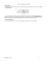
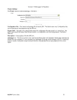
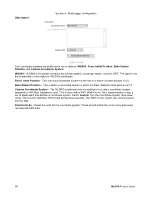
Project Settings 

The 

Project

 options contains datalogger information. 


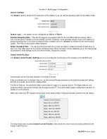
(Figure 4.4.2 B) 

Configuration File


‒ The loaded configuration file for the MLGPS. This field is read-only. Configuration files 

can be browsed for and loaded through the 

 icon. 

Project Path


‒ The path to the default folder where the configuration file was saved to or loaded from. This 

path is also used for all project files that are related to a configuration and monitoring session. This field is 
read-only. 

Description


‒ A description of the MLGPS unit. 

Datalogger ID


‒ The ID is a numeric value used for identifying data in the database. MultiLogger automatically 

assigns the next available ID. Once assigned, the Datalogger ID should not be changed. If an ID is entered by 
a user manually, it should be unique to ensure that the collected data files are associated with the correct 
logger. 


Summary of Contents for MLGPS-P-24S

Page 1: ...MLGPS P 24S User s Guide Hardware Version 2 0 Guide Revision F August 2021...

Page 2: ...y Canary Systems warrants products manufactured by Canary Systems excepting software products to be free from defects in materials and workmanship under normal use and service for twelve 12 months fro...

Page 3: ...users guides Additionally Canary Systems provides additional information beyond the scope of the technical documentation in the form of Application Notes Training Videos and White Papers Visit the Sup...

Page 4: ...the Canary System s website to view and download the most current versions of our technical documentation and user s guides at https canarysystems com support users guides The following documents con...

Page 5: ...e xPico 22 Section 4 MultiLogger Configuration 31 4 1 Overview 31 4 2 Communications Configuration 31 4 3 Base and Rover Station Configuration 36 4 4 Logger Form Features 51 Section 5 Using MicroSD Ca...

Page 6: ...highlighted The unit includes a multi function Global Positioning System GPS receiver module an integrated battery charger for 12V lead acid batteries a micro controller for system measurements and co...

Page 7: ...panel temperature humidity using a built in digital humidity sensor and recording the status of a switch closure input This may be used for intrusion detection or connection of a rain gage Power The M...

Page 8: ...tes the system is powered and operating A fixed green light displays when the GPS receiver is loading RED CHARGE LED A flashing red light indicates the battery charging current Inactive the current is...

Page 9: ...g the microSD mounting the File System and opening the Firmware file to update the NVM memory If only the blue LED is blinking each flash indicates the next 20KB from the Firmware file was stored to N...

Page 10: ...Link yellow Network link status LAN Active yellow Network Activity System Power Voltage 12 VDC 750mA max nominal 70mA 180mA Depending on Offline Mode configuration Batteries up to 24 AHr Pass current...

Page 11: ...e data on potential change in the position of the receivers and therefore the ground or structures they are located upon This data can include velocity of movement direction of movement horizontal ver...

Page 12: ...ifferential GPS relies on a stable point of reference The addition of multiple Base Stations can help to ensure that a stable point of reference is always available Multiple baselines also allow Base...

Page 13: ...Section 1 Introduction MLGPS P User s Guide 13 1 4 Connections Connections to the MLGPS P are provided at the bottom of the enclosure Figure 1 4 A...

Page 14: ...NC TNC GPS Antenna Cable 3m 10 Included 1 Rubber duck 5 5dBi Wi Fi Antenna Included 1 Null Modem Serial Cable Included 1 Standard Serial Cable Included 1 30W Solar Panel Included 1 Solar Panel Ground...

Page 15: ...etation growth construction etc for the site If obstructions are unavoidable the antenna should be positioned so that the obstructions are to its north This is due to the design of the GPS satellite c...

Page 16: ...rates the variability between summer and winter and latitude Insolation is a measure of solar radiation energy received on a given surface and recorded during a given time Figure 2 2 B Insolation thro...

Page 17: ...n the field using a tripod with rock pan and solar panel Tripod Setup 1 Select a site for the tripod that is safe from hazards such as falling rocks and moving vehicles 2 Setup the tripod making sure...

Page 18: ...at between 3 8 and 7 8 of thread is exposed for mounting the antenna 2 Align the mount thread with the metal adaptor on the bottom of the antenna and rotate the antenna clockwise until it is securely...

Page 19: ...applications The adaptor includes a mil spec connector to connect to the bottom of the enclosure Use the appropriate AC power cord for connecting to a standard AC receptacle Contact Canary Systems fo...

Page 20: ...th NO available network the MLGPS still collects data using Offline mode This data can be retrieved manually be retrieved from the microSD card See Section 5 Using MicroSD Card 3 1 Overview There are...

Page 21: ...PuTTY Configuration as follows Set the Serial line to the correct COM port This can be found using Device Manager Set the Baud Rate Speed to 115200 Note If the xPico factory defaults have been applied...

Page 22: ...matically generated XML DOCTYPE configrecord ELEMENT configrecord configgroup ELEMENT configgroup configitem ELEMENT configitem value ELEMENT value PCDATA ATTLIST configrecord version CDATA IMPLIED AT...

Page 23: ...92 168 0 1 value configitem configitem name Hostname value value configitem configitem name Priority value 2 value configitem configitem name Primary DNS value 192 168 0 1 value configitem configitem...

Page 24: ...y value value name WEP Key 2 Key value value name WEP Key 3 Key value value name WEP Key 4 Key value value name WPAx Authentication PSK value value name WPAx Key Type Passphrase value value name WPAx...

Page 25: ...figgroup name Tunnel Connect instance 1 configitem name Mode value Always value configitem configitem name Local Port value 10002 value configitem configgroup configgroup name Tunnel Disconnect instan...

Page 26: ...on This section outlines how to program the xPico radio using CLI commands Enable your terminal window and press ENTER The following prompt should display If the prompt does not delay then check seria...

Page 27: ...Section 3 xPico Configuration MLGPS P User s Guide 27...

Page 28: ...Section 3 xPico Configuration 28 MLGPS P User s Guide...

Page 29: ...start blinking Note If the LAN does NOT start blinking then either the SSID or passphrase was entered incorrectly OR there is another WLAN profile which is active Other WLAN profiles should be delete...

Page 30: ...s To check any setting command space tab Show options for current level Check wireless status config interface wlan0 show Check network status status wlan show Check available networks wlan scan from...

Page 31: ...e Section 4 2 Configure Station as Base or Rover See Section 4 3 Configure Data Collection See Section 4 3 Adjust Advanced Settings optional See Section 4 4 There are many options available to optimiz...

Page 32: ...elect TCP IP Socket from the list of available devices and click Accept Figure 4 2 B The Add new Gateway or Device form used to select a TCP IP Socket Note Stations that do not have any available netw...

Page 33: ...PS P User s Guide 33 The Network Manager will update with the new Socket communication type and node This can be renamed by double clicking the node in the network tree slowly Figure 4 2 C The new Soc...

Page 34: ...form Expand the Canary Systems group and select MLGPS Click Accept Figure 4 2 D The Add new Gateway or Device form with the MLGPS device and Accept button highlighted A prompt is displayed to Select...

Page 35: ...d it should not be changed However if the name does need to be changed in the future contact Canary Systems for assistance Next update the IP Address edit with the assigned IP address for the xPico in...

Page 36: ...rt as possible and to mitigate potential errors due to movement in single Base Stations MLGPS supports differential processing with multiple baselines Each MLGPS unit can be configured as a Base or Ro...

Page 37: ...ce of the antenna Please note that stopping Base Station logging will impact all Rover Station solutions This situation may result in outliers or gaps in solutions data Clear purges the current positi...

Page 38: ...em and antenna type optional Enter the station s Initial Position if known or determine through the Averaging function Start data collection Note Clicking Start before setting the base station s Curre...

Page 39: ...or when in Monitor Mode Otherwise an interval should be selected to conserve battery life Note Always On must be selected for Offline Mode compatible devices that are missing the SD card older MLGPS m...

Page 40: ...n Enter Coordinate System and Antenna Settings It is recommended during the initial configuration of the Base Station to specify the coordinate system and the GPS antenna type in the Advanced Settings...

Page 41: ...nates can be manually entered in the Station Initial Position fields Figure 4 3 1 G The Station Initial Position options of the Logger form If the Base Station Initial Position is unknown it should be...

Page 42: ...server in the background When the position is calculated the Average function stops and results can be evaluated The Position Convergence chart highlighted in Figure 4 3 1 I shows convergence for all...

Page 43: ...ata collection for the station Once the Base Station is collecting data Rover Stations or additional Base Stations may be configured If MultiLogger is unable to connect to the datalogger at the time t...

Page 44: ...tion Type to Rover and configure Position Sampling Rate Configure Offline Mode if compatible Configure the solutions for the Rover positional data for each baseline Enter the coordinate system and ant...

Page 45: ...is recommended that Rover Stations keep a default value of 1 second for the Position Sampling Rate for the best solution quality more samples per period results in a more precise solution For the Sta...

Page 46: ...and the solution will then be processed using that Base Station s positional data Figure 4 3 1 C shows a Rover with 6 solutions configured three for each of its two base stations Figure 4 3 2 C Each...

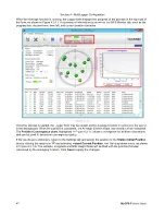
Page 47: ...it is recommended to use the first reading from the solution with the longest interval as it may guarantee position accuracy in the sub centimeter range This means that after the Rover Start program i...

Page 48: ...button to begin collecting and processing data It is important to configure the Data Collection tab of MultiLogger for each configured station See Data Collection for more on that process If MultiLog...

Page 49: ...work Manager Click on the Gateway node in the Network Configuration tree Notice the Database Alias drop down list highlighted in Figure 4 3 2 A Select the database into which the data will be imported...

Page 50: ...utomatic import of the collected data into the selected database Configure the Interval for collection and make sure Resume Schedule After Delayed Retries is checked to ensure data collection will con...

Page 51: ...m The top right of the logger form under the toolbar indicates the program status as well as if the MLGPS module is Offline Mode compatible OFFLINE The MLGPS module is compatible with Offline mode and...

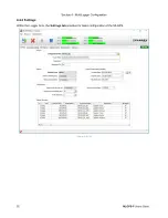
Page 52: ...Section 4 MultiLogger Configuration 52 MLGPS P User s Guide 4 4 2 Settings Within the Logger form the Settings tab provides for basic configuration of the MLGPS Figure 4 4 2 A...

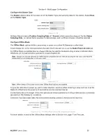
Page 53: ...e configuration file was saved to or loaded from This path is also used for all project files that are related to a configuration and monitoring session This field is read only Description A descripti...

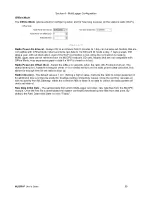
Page 54: ...nd will be imported into the database as is An interval that is practical for data storage such as fifteen minutes should be selected Station Initial Position The Station Initial Position Settings all...

Page 55: ...s lost Radio Power On Offset Sec Select the Offset in seconds when the radio Wi Fi should turn on The default setting is 0 however setting an offset of 8 or similar will turn on the radio prior to dat...

Page 56: ...pproximate precision depending on the averaging interval for four example periods Interval Precision 15 Minutes 25 mm 1 Hour 20 mm 6 Hours 10 mm 24 Hours 2 5 mm Table 4 4 2 A Base Station For static s...

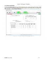
Page 57: ...ings tab has several features that allow users to optimize settings for the station and its data These features are Antenna Settings Coordinate System Rover Position Post Processing GPS Data Archiving...

Page 58: ...tial position is 0 0 Base Station Position This creates a coordinate system in which the Base Station s initial position is 0 0 Custom Coordinate System The MLGPS coordinates can be matched to a custo...

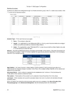
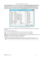
Page 59: ...tion Elements window The Data Collection Elements window allows users to configure the settings for each Data Collection Element as follows ID The Data Collection Element type Name The name of the Dat...

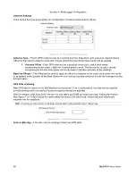
Page 60: ...Offsets The Offset grid is used to apply an offset to a baseline in the case that a correction needs to be applied to the position of the Base Station without interrupting data collection to redo the...

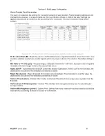
Page 61: ...etting is 5 Min Ratio to Fix Ambiguity Integer ambiguity validation threshold for ratio test It uses the ratio of squared residuals of the best integer vector to the second best vector Reject GDOP Rej...

Page 62: ...ger form of MultiLogger Position Displays the instant position calculated by the receiver itself This information in general is equal to a single solution result Hardware Solution Details Displays inf...

Page 63: ...as follows PRN This stands for the unique pseudo random noise sequence transmitted by each satellite that allows it to be differentiated from other satellites Ch The channel number of the receiver th...

Page 64: ...er form of MultiLogger for visualizing solution results The main line chart is divided into three parts Delta North Delta East and Delta Height To the right of the line chart are three small scatter p...

Page 65: ...lution as well as using the marking tool in the solution line chart To mark the period on the chart press and hold the Shift key and then left click the start date of the period and the end date of th...

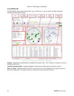
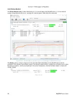
Page 66: ...ection Elements Figure 4 4 6 A The Status Monitor tab of the Logger form of MultiLogger for MLGPS device status The Status options shown in Figure 4 4 6 A provides basic information on the MLGPS devic...

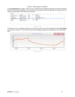
Page 67: ...nd Battery_Volts along with the timestamp of their last readings the values of the last readings the Elements units and their descriptions Figure 4 4 6 C The Elements in the Last Reading table can be...

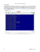
Page 68: ...re familiar with a GPS receiver command system Due to the asynchronous design of a GPS receiver protocol commands should be typed in the Command drop down at the bottom of the form and then the Send C...

Page 69: ...HELP Show list of commands MLGPS_HMD Get humidity MLGPS_LIC Turn on off Low Insolation Compensation Syntax MLGPS_LIC N Y MLGPS_LOGL Get Set logging level Syntax MLGPS_LOGL DEBUG INFO WARNING ERROR FAT...

Page 70: ...fore beginning import of data into the database Upon review of the results outlier filter parameters may need to be readjusted and the solution can be reprocessed afterwards Selecting the Reprocess So...

Page 71: ...running the Solution Progress block displays on the Logger toolbar It respectively indicates the raw GPS data collection progress for all solutions in terms of time When all necessary data for a solut...

Page 72: ...the MLGPS Stations and files can be manually collected In the event files need to be retrieved manually from the microSD card there are important steps that should be followed 5 1 Replacing the Micro...

Page 73: ...Figure 5 1 B 3 After pressing the Eject button for firmware V3 0 34 or newer wait for the LED lights to indicate the microSD is ready to be removed When the Power LED starts flashing this means the ca...

Page 74: ...are labeled according to the Station name as defined in MultiLogger and the device Serial Number listed in MultiLogger and on the MLGPS Unit s label This is important to keep cards organized Note Atte...

Page 75: ...he SD card not just individual files to your local machine and not directly into the MLGateway folder When selecting the folders to be imported keep in mind raw files are named using times stamps in G...

Page 76: ...on and test power with a digital voltmeter Check the battery terminals directly it should read between 12 5 13 5VDC If battery power is adequate verify the Power switches are turned ON If power is on...

Page 77: ...er Lantronix supports the latest version of Internet Explorer Mozilla Firefox Safari and Chrome a Enter the IP address or hostname of the xPico Wi Fi device in the address bar The IP address may have...

Page 78: ...s Guide 2 Once connecting using the browser interface click QuickConnect at the top left of the window to display a list of all networks visible to the xPico module Figure A 2 3 From the list provided...

Page 79: ...de 79 4 Enter the correct WPA password and click Apply IT departments on site will provide Desired Network IP address for assignment Network Default Gateway WPA Passphrase 5 Click Yes on the message b...

Page 80: ...eview the additional network settings and make any necessary updates When everything is correctly configured for the desired network click Submit WARNING After submitting your results it is important...

Page 81: ...Appendix A xPico Connection Via Browser MLGPS P User s Guide 81 7 Check that the Network Configurations are correct by navigating to the Network tab and selecting wlan0 and Configuration Figure A 5...

Page 82: ...er 82 MLGPS P User s Guide 8 Network Connections should be as follows State Enabled DHCP Client Disabled IP Address Insert given IP from IT department Default Gateway Insert given Gateway from IT depa...

Page 83: ...be rebooted to put these changes into effect This can be done through the web interface a On the web interface select the Device button on the side panel and choose Reboot b After clicking Reboot cli...

Page 84: ...be enabled for communications Follow these steps to enable communication between the MLGPS unit to an LTE Gateway such as the AirLink RV50 1 Using the GPS RS 232 port on the right side of the device...

Page 85: ...rk with a Raven wireless device 9 The null modem cable can be disconnected from your computer 10 Using a serial cable connect the AirLink RV50 radio to the MLGPS using the same GPS RS 232 port For add...

Page 86: ...ffline Only Stations If configuring an MLGPS station that will run entirely offline it can be configured using a COM rather than the TCP IP Socket Figure C 1 The Network Manager is updated with the ne...

Page 87: ...ly Stations MLGPS P User s Guide 87 Expand the Canary Systems group and select MLGPS Click Accept Figure C 3 A prompt is displayed to Select Logger Configuration File Select Assign a new Configuration...

Page 88: ...meaningful for in field location Note that this automatically renames the configuration file for the unit to the name entered Note Once the name is set and saved it should not be changed However if t...

Page 89: ...able 5 Open MultiLogger and check the results If satisfactory navigate to the Settings tab and assign the position to the Instant Current Position as the Station Position and Save the MLGPS logger for...

Page 90: ...s instruct you to disconnect it 2 Open MultiLogger open the Stations logger form and navigate to the GPS Monitor tab 3 Record the position These coordinates should be manually entered as the Station I...

Page 91: ...r between a Base Station at a known location and a Rover at a to be calculated position This distance should be kept as small as possible with a maximum distance of 10km in order to assure that the Ba...

Page 92: ...times when ambiguities are resolved for and can be used to achieve more accurate results than the pseudorange despite being more time consuming Carrier Phase Transmission See Carrier Signals Carrier...

Page 93: ...is noticed and accounted for Without multiple baselines this change would be assumed to be an atmospheric error and would be factored into the Rover s readings causing additional error Dilution of Pr...

Page 94: ...e dimensions in real time GNSS GPS Monitoring The use of GNSS s or specifically GPS to provide 3D positioning data for GNSS receivers affixed to a monitored structure Deformation can be monitored over...

Page 95: ...of a satellite decreases as the signal is travelling through the ionosphere for longer Additionally the Ionosphere is variable and can experience different levels of ionization depending on time of d...

Page 96: ...t four separate satellites it can determine its own position on the Earth in three dimensions One method to determine this distance is the pseudorange The pseudorange is the pseudo distance between th...

Page 97: ...f positioning Sky View can be obstructed by objects such as mountains buildings or vegetation Note that due to constellation design there is a hole in the sky to the North in the Northern Hemisphere a...

Page 98: ...c clock onboard When the satellite broadcasts its signal it includes the time that the signal is broadcast according to its atomic clock This is the time signal Trilateration A geometric method of det...

Reviews: