


12
NOTE
Air Intake material must be of a type listed by a nationally recognized testing agency
1.
PVC
Non-Foam Core Pipe.
2.
CPVC
Non-Foam Core Pipe.
3.
Polypropylene
4.
ABS
(Acrylonitrile-Butadiene-Styrene)
Single Wall air intake pipes are to be insulated 5 feet from wall toward the interior of the building to minimize external sweating.
2.1.4
VENT TERMINATION CLEARANCES
•
Do not terminate the vent in a window well, stairwell, alcove, courtyard or other recessed area. The vent cannot terminate below
grade. The bottom of the vent terminal shall be located at least 12 inches (30 cm) above grade and above normal snow levels.
In all cases, the appliance shall be installed in accordance with local codes.
•
The vent outlet MUST NOT terminate below a forced air inlet at any distance.
•
The vent cannot terminate below grade. Position the vent termination where vapors will not damage walls or plants or may
otherwise be objectionable.
•
The vent terminal shall not be installed closer than 3 feet (1 m) from an inside corner of an L-shaped structure, window well,
stairwell, alcove, courtyard or other recessed area as wind eddies could affect boiler performance or cause recirculation.
•
DO NOT terminate closer than 4 feet (1.25 m) horizontally and vertically from any electric meter, gas meter, regulator, relief
valve, or other equipment. In all cases, local codes take precedence.
•
Position terminations so they are not likely to be damaged by foreign objects or exposed to a build-up of debris.
•
The vent piping must terminate in an elbow pointed outward or away from the air inlet.
•
To avoid a blocked flue condition, keep the vent cap/terminal clear of snow, ice, leaves, debris etc.
•
Flue gases from this appliance may contain large amounts of water vapor that will form a white plume in winter. Plume could
obstruct a window view.
•
Flue gas condensate can freeze on exterior walls or on the vent cap. Frozen condensate on the vent cap can result in a blocked
flue condition. Some discoloration to exterior building surfaces can be expected. Adjacent brick or masonry surfaces should be
protected with a rust resistant sheet metal plate.
2.1.5
INLET CAP FOR ROOFTOP TERMINATION
The air inlet cap consists of two 90° elbows installed at the point of termination for the air inlet pipe. The first 90° elbow is installed on the
rooftop at the highest vertical point of the air inlet pipe and turned horizontal; the second 90° elbow is screened and is installed on the
horizontal outlet of the first elbow and turned down. A 90° elbow and a 90° street elbow may be used to make this assembly. If a straight
piece of pipe is used between the two elbows, it should not exceed 6” (150 mm) in length.
2.1.6
LOCATION OF A ROOFTOP AIR INLET AND VENT CAPS
•
The point of termination for the combustion air inlet cap MUST be at least 3 feet (0.91 m) below the point of flue gas termination
(vent cap) if it is located within a 5 foot (1.5 m) radius of the flue outlet. Use care to ensure that the 90° elbow assembly is
properly installed on the air inlet pipe.
•
The termination point of the combustion air inlet cap must be installed at least 3 feet (0.91 m) above the rooftop and above
normal snow levels.
•
The vent cap assembly MUST be listed by nationally recognized agencies.
•
The combustion air cap and vent cap MUST be located on the same roof top surface and in the same pressure zone.
•
Combustion air supplied from outdoors must be free of contaminants. To prevent recirculation of flue products into the
combustion air inlet, follow all instructions in this section.
•
Incorrect installation and/or location of the air inlet cap can allow flue products to be drawn back into the appliance. This can
result in incomplete combustion and potentially hazardous levels of carbon monoxide in the flue products. This will cause
operational problems with the appliance and if left uncorrected, will lead to conditions that can cause personal injury or death.
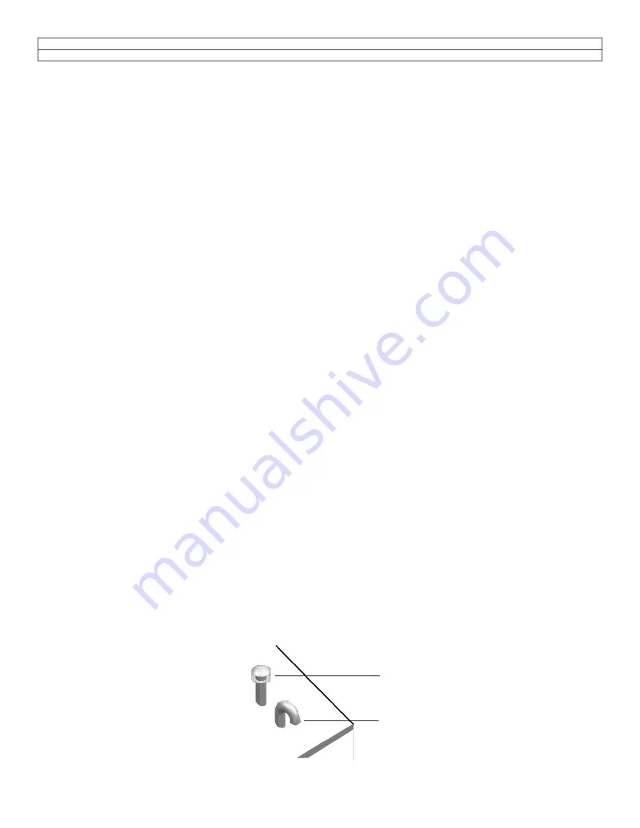
Figure 6: Vertical Direct Venting Configuration
Vent
Air Intake
Air inlet must
be 36” min.
below vent
opening
Summary of Contents for Avenger Series
Page 2: ......
Page 35: ...30 Figure 21 Recommended Piping with Reverse Return and Variable Primary Flow...
Page 84: ...79 Figure B BLOWER BURNER ASSEMBLY...
Page 87: ...82 Figure C TYPICAL GAS TRAIN AR1000 AR3000 Figure D TYPICAL GAS TRAIN AR3500 AR4000...
Page 89: ...84 Figure E CONTROL BOARD ASSEMBLY...
Page 92: ...87 PART 13 ELECTRICAL DIAGRAMS...
Page 93: ...88...
Page 94: ...89...
Page 95: ...90...
Page 96: ...91...
Page 97: ...92...
Page 98: ...93...
Page 99: ...94...
Page 100: ...95...
Page 101: ...96...
Page 102: ...97...
Page 103: ...98...
Page 104: ...99...
Page 105: ...100...
Page 106: ...101...


