background image


SECTION 3: PROGRAMS & STATIONS                                           


®


making

        since 1986


water work


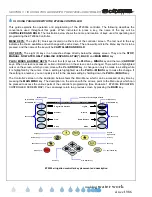
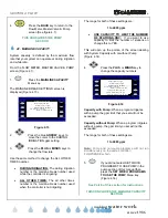
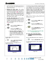
5.                 When at the Station Programming  
                      screen, the two (2) top right Menu keys  
                      are used for 

STATION UP

 and 


STATION DOWN

 . The following  

                      explains each setting on the STATION  
                      PROGRAMMING screen. 


STATION:

 Indicates the current station 

number (Station 1 is the example in figure 
3.2). 


PROG: 

Indicates the program that the 

current station is assigned to (Program A 
is the example in figure 3.2). 


TOTAL MINS: 

The total amount of 

irrigation time that will be applied in each 
24 our watering period. 


MINS PER CYCLE: 

The amount of 

irrigation time applied in each cycle of a 24 
hour watering period. 


SOAK-IN TIME:

 The amount of time (In 

Minutes) between multiple cycle starts. 


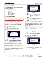
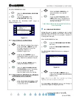
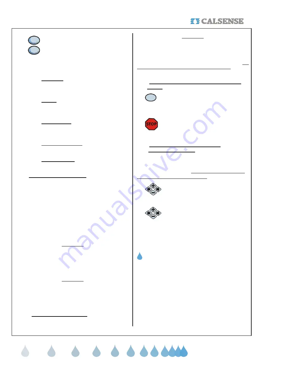
3B.1  Cycle and soak examples: 


In the example shown in figure 3.2, station 1 will 
irrigate for 5.0 minutes (the Mins per Cycle setting) 
then wait 60 minutes (the Soak-in Time setting), it will 
repeat the process two (2) more times until the total 
irrigation applied is 15 minutes ( the Total Mins 
setting), this feature is called Cycle and Soak. Each 
station’s Cycle and Soak setting can be set 
independent of any other station’s settings. The 
following shows some examples of Cycle and Soak 
settings: 
 

Example 1 


Total Mins:            10.0   
Mins per Cycle:     2.0   
Soak-in Time:       


15    

 
In this example the controller will irrigate 5 cycles of 2 minutes, for a 
total of 10 minutes with a soak in time of 15 minutes between cycles. 

Example 2 


Total Mins:            10.0


Mins per Cycle:


10.0 

Soak-in Time:


5.0 


In this example the total minutes and the minutes per cycle are the 
same, therefore the controller will irrigate only one cycle of ten 
minutes. 

The soak in time will be ignored


Example 3 


Total Mins:


10.0


Mins per Cycle:


20.0 


Soak-in Time:


10  


In this example the controller will irrigate 1 cycle of 10 minutes. 

The 

Mins per Cycle Time and Soak-In Time will be ignored
.     


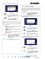
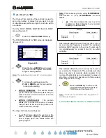
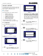
3B.2  Test a Station at the Station Programming  
        Screen 


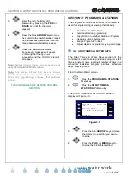
1. 

      Press the 

TEST 

Menu key to turn the  

                     current station on. The run time will be  
                     the time set at the Valve Testing   
                     screen. 

2. 

     Pressing  the 

STOP

 key at anytime will  

                     end the test. 
 

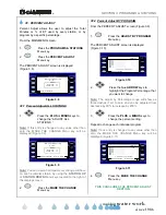
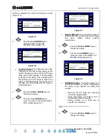
3B.3  Set No Water Days at the Station  
         Programming Screen 
 

No Water Days gives you the ability to turn a specific 
station off for a certain amount of days consecutively 
starting from today’s date. This setting will only affect 
the station selected on the screen. 


1. 

     To turn the current station off for 1 to 

                         31 days, press the blue 

ARROW

 keys  

                         to highlight the No Water Day setting. 

2. 

      Press the 

PLUS

 or 

MINUS 

keys to set  

                         the number of No Water Days 
                         desired. 
 

THIS CONCLUDES THE STATION PROGRAMMING 

SECTION


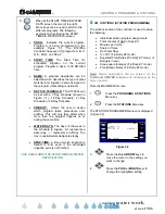
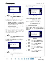
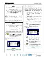
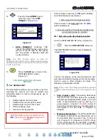
3C.  STATION-TO-STATION COPY 


The Station to Station Copy feature allows you to copy 
programming from one station to another station, all 
stations, or all of the stations in a particular program. 


The settings that are copied are: 
 

 Total 

Minutes 

(except in Daily ET mode) 


Minutes Per Cycle 

 Soak-In 

Time 


Summary of Contents for ET2000e

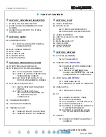
Page 1: ...AMMING GUIDE making since 1986 water work ET2000e IRRIGATION CONTROLLER PROGRAMMING GUIDE For use with ET2000e irrigation controllers running on firmware version 605 a and above CHANGE 1 INCORPORATED...

Page 2: ...LLER 3D PROGRAM PRIORITIES 3E STATIONS BY PROGRAM 3F PERCENT ADJUST 3F 1 PERCENT ADJUST ALL STATIONS 3F 2 PERCENT ADJUST BY PROGRAM SECTION 4 FLOW 4A TRACK ESTIMATED 4B POC MV FM 4B 1 FMBX FLOW METER...

Page 3: ...A LIGHTS CIRCUIT SECTION 8 RADIO REMOTE RRe OPTION 8A ENABLE RADIO REMOTE SECTION 9 NO WATER KEY 9A NO WATER KEY DESCRIPTION 9A 1 TURN CONTROLLER OFF 9A 2 APPLY NO WATER DAYS TO PROGRAM 9A 3 NO WATER...

Page 4: ...ERCENT ADJUST ALL STATIONS CHANGE 1 30 MARCH 2007 3F 2 PERCENT ADJUST BY PROGRAM CHANGE 1 30 MARCH 2007 SECTION 4 FLOW 4A TRACK ESTIMATED CHANGE 1 30 MARCH 2007 4B POC MV FM CHANGE 1 30 MARCH 2007 4B...

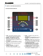
Page 5: ...he controller Help screens 5 ENGLISH ESPANOL The ENGLISH ESPANOL key allows you to toggle the screen text between English and Spanish 6 BACK The BACK key will go back to the previous screen 7 MAIN MEN...

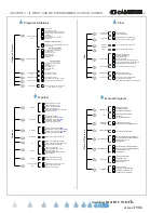
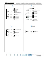
Page 6: ...By Monthly Direct Enter Calculate Budget Select To Use Moisture Sensors Assign Sensor Slaving To Valves Select State County And City For ET Enter Your Own ET Numbers View Historical ET Totals Moistur...

Page 7: ...Separate Lights Schedules L Manually Start Lights For 4 hours L Radio Remote Enable Radio Remote RRe Station Alerts View And Clear Station Alerts Controller Alerts View And Clear Controller Alerts Vie...

Page 8: ...ccessed certain information on the screen can be changed There will be a highlighted cursor on the screen which you can move with either ARROW key A change can only be made to a setting while it is hi...

Page 9: ...11 for detailed instructions The communication screen should look like the one in Figure 2 2 if your controller does not have the FLOWSENSE option NO Communications Address A ET2000e 40 M SR FL 605 b...

Page 10: ...re to SET IT Use day Light Savings YES Date Time to Set DATE TIME Apr 03 2006 Mon 10 26 40AM Current Date Time Figure 2 5 3 Press the PLUS or MINUS keys to change the Month setting 4 Press the blue AR...

Page 11: ...the MAIN MENU screen 1 Press the SETUP Menu key 2 Press the 12 MONTH MODE Menu key The USE OF 12 MONTH MODE screen is displayed Figure 2 7 USE OF 12 MONTH MODE Daily ET may not be necessary Using 12 M...

Page 12: ...ion of the controller is used for programming or viewing the following Start Times Water Days Individual station programming Copy Station to another Station or Program Viewing stations by program Assi...

Page 13: ...week in the schedule to irrigate on represents a water day represents an off day The day in capital letters designates today STOP TIME A time at which irrigation is forced to end even if the schedule...

Page 14: ...or a total of 10 minutes with a soak in time of 15 minutes between cycles Example 2 Total Mins 10 0 Mins per Cycle 10 0 Soak in Time 5 0 In this example the total minutes and the minutes per cycle are...

Page 15: ...ess any key to continue 3C 2 Copy a Station to All Stations on a Program or All Stations on the Controller 1 At the STATION TO STATION COPY screen press the blue ARROW keys to move the cursor 2 Press...

Page 16: ...each program THIS CONCLUDES THE PROGRAM PRIORITIES SECTION 3E STATIONS BY PROGRAM This section of the controller allows you to view each station by program that it is currently assigned to You can al...

Page 17: ...ation by using the STATION UP or STATION DOWN Menu keys located to the right of the display screen 2 Press the MAKE THE CHANGE Menu key 3F 2 Percent Adjust BY PROGRAM From the PERCENT ADJUST screen Fi...

Page 18: ...you are interested in flow reports Do you want to set the expected Figure 4 2 2 Press the PLUS or MINUS keys to change the DO YOU WANT TO SET THE EXPECTED FLOW RATES FOR REPORTS setting Note When the...

Page 19: ...4 5 Flow Meter in use NO Master valve is NORMALLY CLOSED POINT OF CONNECTION MV FM Figure 4 5 4 Press the PLUS or MINUS keys to change the FLOW METER IN USE setting The POINT OF CONNECTION screen wil...

Page 20: ...the controller to learn the expected flow rate for each station It is only available if a flow meter is in use From the MAIN MENU screen 1 Press the FLOW Menu key The FLOW METER MASTER VALVE PUMP scr...

Page 21: ...e PLUS or MINUS keys to set the desired time in seconds Note Use this same method to change the VALVE CLOSE TIME for Program A and then repeat these steps for each program on the list 5 Press the BACK...

Page 22: ...not irrigating The range for both of these settings are 1 to 4000 gpm USE CAPACITY TO LIMIT THE NUMBER OF STATIONS ON If you want to use capacity to limit the number of stations on change this to YES...

Page 23: ...to come on at a time within the controller The range for these two settings are 1 4 This choice allows the user to set the limit of stations operating simultaneously from a single up to four valves wi...

Page 24: ...gs press the PLUS or MINUS keys for any number to change the setting Below This section allows you to enter the fluctuation range for the low end of your normal operating flow Use the and entries to s...

Page 25: ...Valve Mainline Capacity Figure 4 18 THIS CONCLUDES THE FLOW CHECKING SECTION 4I ALERT ACTIONS The Alert Actions section of the controller allows you to setup the way in which you want the controller...

Page 26: ...THER SETUP screen is displayed Figure 5 2 WEATHER SETUP ET Gage ET Rain Bucket Budget Rain Switch Wind Gage Moisture Figure 5 2 2 Press the ET GAGE Menu key The ET GAGE screen is displayed Figure 5 3...

Page 27: ...hange the setting 8 Press the blue ARROW keys to move the cursor to the GAGE IS 99 FULL setting Figure 5 7 Irrigation Day is from 8 00PM to 8 00PM Is there an ET Gage YES Log Pulses NO Gage is 99 full...

Page 28: ...d If the controller in use does not have the RB option installed see 2 Rain setup without Rain Bucket installed and you are sharing rain to controller 5B 1 Rain setup with Rain Bucket installed From t...

Page 29: ...played Figure 5 11 PROG A YES Rain causes negative hold over to build USE OF RAIN BY PROGRAM which acts to cancel irrigation DRIP 2 YES Allow RAIN on the following PROG B YES PROG C YES PROG D YES PRO...

Page 30: ...YES DRIP 1 YES Figure 5 13 Here you will have the option of enabling or disabling the use of negative hold over rain for any of the controller s seven programs If you select YES rain negative hold ov...

Page 31: ...set the Miles Per Hour that you want the controller to resume irrigation at Figure 5 17 WIND GAGE YES than 15 MPH than 10 MPH Is Controller Wired to a WIND GAGE SETUP PAUSE IRRIGATION when wind is hi...

Page 32: ...oid NO CURRENT rain switch detects rain Is the controller connected to RAIN SWITCH SETUP Irrigation will be STOPPED when the Figure 5 20 THIS CONCLUDES THE RAIN SWITCH SECTION 5E ET The ET section of...

Page 33: ...NO PROG B NO IRRIGATE USING USE DAILY ET SETUP 8 00PM TO 8 00PM NO PROGRAM TAG PROG C NO PROG E NO Crop Coefficients Figure 5 23 5E 4 Crop Coefficients This setting is used to adjust ET for a specifi...

Page 34: ...ow rates by Measuring Station Flow Rates The second method may provide more accurate results by using the irrigation system s water meter to calculate flow rates Use the following procedure o Determin...

Page 35: ...f Daily ET Estimated Mins This is the total estimated minutes for this station using Daily ET calculated automatically of ET This value can be adjusted to increase or decrease the amount of estimated...

Page 36: ...g the total square footage and your city ET 1 In the WATER USE BUDGET screen Figure 5 28 In the OPTIONS setting press the PLUS or MINUS keys to change the setting to CONTROLLER WILL AUTOMATICALLY CALC...

Page 37: ...The MOISTURE SENSING SETUP screen is displayed Figure 5 31 Moisture Sensing in Use NO MOISTURE SENSING SETUP Figure 5 31 If you are currently using Moisture sensors on this controller then change the...

Page 38: ...02 03 04 05 06 07 08 09 10 Sensor 01 02 03 04 05 06 07 08 09 10 becomes Station 01 02 03 04 05 06 07 08 09 10 Sensor 01 02 03 04 03 03 07 03 09 10 Note In the example above station 03 is the Master s...

Page 39: ...the slave area is too dry adjust it s maximum time to 10 more If the area is too wet decrease it by the same percentage In both cases the area should be rechecked after another few weeks with readjus...

Page 40: ...activate test The screen will show READING SENSOR ON please wait Less than 15 seconds for which ever station you selected After a brief test the STATION PROGRAMMING screen will appear with the Moistu...

Page 41: ...er stores historical ET information for several states counties and numerous cities Select the area that most closely represents your location Figure 5 45 Source Supplied ET for Your City State CALIFO...

Page 42: ...2 Press the REPORTS Menu key The REPORTS menu screen is displayed Figure 6 2 REPORTS This Month Last Month Alerts 24 Month Station History ET Rain Tables Live Screens Hold Over Use vs Budget Figure 6...

Page 43: ...on Note These entries can be viewed in Hundreds of Cubic Feet also THIS CONCLUDES THE 24 MONTH SECTION 6C HOLD OVER Hold Over occurs if the controllers irrigation cycle is forced to end before it has...

Page 44: ...ET Table h Historical This means the ET number was retrieved from the historical ET table g ET Gage This means the ET number was retrieved from an actual real time ET gage e Edited This means the ET...

Page 45: ...is available on the STATUS screen when the ALERTS MENU key is pressed it will cause the MOST RECENT ALERTS screen to come up if not the ALERTS screen will appear as in figure 6 7 The ALERTS screen is...

Page 46: ...ISTORY Date Time HI GPM LO SET READ FLAG FLOW MOISTURE 11 21 2 20PM 19 24 29 99 41 11 19 2 20PM 19 24 29 99 41 11 17 2 20PM 19 24 29 99 41 11 20 2 20PM 19 24 29 99 41 Page Left 11 16 2 20PM 19 24 29 9...

Page 47: ...he LIVE SCREENS Menu key to access the REAL TIME DISPLAYS screen Figure 6 13 2 Press the DETAILS Menu key to access the IRRIGATION DETAILS screen Figure 6 15 Note From here you can view the IRRIGATION...

Page 48: ...ress the REAL TIME POC FLOW Menu key The REAL TIME POC FLOW screen is displayed Figure 6 17 If all three POC settings are used with irrigation the screen will appear as shown below Figure 6 17 POC 2 3...

Page 49: ...er via Command Center software Once you have selected the lights program that you want to use 3 Press the blue ARROW keys to highlight the date entry You can select any date between now and two weeks...

Page 50: ...ON RESUME button 3 Scroll down to CHANGE LIST Figure 8 2 CHANGE LIST Add via Controller Add via PC Delete Controllers Figure 8 2 4 Press the SELECT button 5 Move the cursor to ADD VIA CONTROLLER Figur...

Page 51: ...e blue ARROW keys to highlight which program to set the No Water Days for 4 Press the PLUS or MINUS keys to select the desired program or all stations 5 Press the APPLY NO WATER DAYS Menu key In Figur...

Page 52: ...l Water Station 1 for 3 0 mins MANUAL IRRIGATION Cycle Soak During Manual NO Manual Water ALL Stations Figure 10 2 10A 1 Manual Water a Station From the MANUAL IRRIGATION screen Figure 10 2 1 Press th...

Page 53: ...er will learn the expected flow rate for each station on each program selected Only available if a flow meter is installed From the VALVE TESTING screen Figure 10 4 1 Press the PLUS or MINUS keys to c...

Page 54: ...AT SUN Figure 10 6 2 Press the PLUS or MINUS keys to change the Open master valve time 3 Press the blue ARROW keys to change from the open and close entry and to change from one day to the next Note T...

Page 55: ...he blue ARROW keys to highlight the Run setting 7 Press the PLUS or MINUS keys to set the amount of days that you want the program to run The End date will change automatically Note If you want the sc...

Page 56: ...will not begin Note When countdown has completed the controller will take you to the Irrigation details screen THIS CONCLUDES THE WALK THRU SECTION 10H USE HOLD OVER Hold Over time is generated whenev...

Page 57: ...s between multiple controllers Eliminates relays when sharing pumps or master valves with several controllers Manages the number of valves ON based upon flow capacities Water management capabilities w...

Page 58: ...s communications information 6 Press the CONTROLLER INFO Menu key to go to the PART SERIAL NUMBERS screen Figure 11 3 Note This will allow you to look at the controller s ROM version Baud Rates Part...

Page 59: ...t a Time Master Valve Mainline Capacity Alert Actions Flow Checking FLOW METER MASTER VALVE PUMP Valve Close Times Line Fill Flow Meter Figure 11 5 The MAINLINE BREAK SETTINGS screen is displayed Figu...

Page 60: ...g is set to NO on a program the pump output will not activate when a station on that program is activated 7 Press the PLUS or MINUS keys to change any program setting 11 B 2 Flow Checking Flow checkin...

Page 61: ...pm 2nd From To This section allows you to set the fluctuation limits for the high end of your medium flowing valves In this box you want to enter the normal operating range of water flow Then in the a...

Page 62: ...program WITHIN CONTROLLER This section allows you to choose the amount of valves that you want to set as a limit to come on at a time within the controller Example Within Program Within Controller Pro...

Page 63: ...keys to change the MASTER VALVE IS setting The Master Valve default setting is for a normally closed Master Valve There are two 2 settings NORMALLY CLOSED A normally closed Master Valve is in the clo...

Page 64: ...SS FLOW METER 3 PLASTIC FLOW METER Figure 12 5 12B Point of Connection 2 3 POC 2 3 POC 2 3 can be set up individually for use with irrigation or for non irrigation use They can also have individual se...

Page 65: ...cheduled periods of time The range for both of these settings are 1 to 4000 gpm 12B 3 Use Master Valve for x xx hours This setting can be used to open a normally closed Master Valve on Point of connec...

Page 66: ...or 0h 0m 0h 0m oh 0m 0h 0m press BACK when schedule is complete THU FRI SAT Use at 12 00PM 12 0PM 12 00PM for 0h 0m 0h 0m oh 0m Figure 12 10 2 Press the blue ARROW keys to move the cursor to the desir...

Page 67: ...__________________________________ __________________________________________ __________________________________________ __________________________________________ ____________________________________...

Page 68: ...ons 200 200Gallons Within Program 1 4 valves X based on system capacity and electrical limit 1 4 valves X based on system capacity and electrical limit On At A Time Within Controller System 1 4 valves...

Page 69: ...ime Rain Switch A Use Of Rain By Program N POC MV FM C Line Fill Valve Close Times C Alert Action ET Budget Moisture B ET State County City Copy Station To Station H Set Valve Run Times Station Progra...

Page 70: ...ENCLOSURE 2 ET2000e IRRIGATION CONTROLLER SCREEN MAP making since 1986 water work...

Page 71: ...ed and this valve failed the LOW FLOW test The action taken is controlled by the Alert Actions settings H High Flow During normally scheduled irrigation or during scheduled manual hold over flow was t...

Page 72: ...nsor Max water Days Set While using moisture sensing MAX WATER was set causing this station to irrigate all of its normally scheduled irrigation regardless of what the moisture sensor said to do V Mas...

Page 73: ...ng below the minimum ET allowed by the user Rain Table Codes LETTER DESCRIPTION DEFINITION o Original This value is zero no usable rain it has no effect on irrigation run times m Below Minimum The bel...

Page 74: ...ES making since 1986 water work ENCLOSURE 4 STATION WIRING COLOR CODES 2075 Corte del Nogal Suite P Carlsbad CA 92011 1 800 572 8608 FAX 1 760 438 2619 www calsense com Stock Number PG4 IC D2 Rev 03 0...

Reviews: