Page 26 of 41
GB
INSTRUCTION, USE AND
MAINTENANCE MANUAL
IN ORDER TO ALLOW THE AIR
JET TO BREAK BOTH BEADS,
DO NOT KEEP THE BEAD LIFTED
FORCING IT.
• Press completely downwards the inflating pedal, in
order to release a high pressure air jet through the
tubeless inflation nozzle.
• Keep partially pressed downwards the inflating pedal
to inflate the tyre and place the beads in their seats.
DO NOT EXCEED THE PRE-AR-
RANGED PRESSURE VALUES
WHILE SEALING THE BEAD.
• After the beads take place in their own seat, discon-
nect the inflating terminal and install again the valve
gear, that was removed previously.
Then connect the inflating terminal and inflate the
tyre with the required pressure.
IF THE TYRE GETS INFLATED TO
MUCH, IT IS POSSIBLE TO EX-
HAUST THE AIR FROM THE TYRE,
BY PUSHING THE MANUAL DE-
FLATING PUSH-BUTTON LOCATED
UNDER THE PRESSURE GAUGE.
• Disconnect the inflation terminal from the valve.
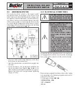
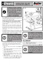
Fig.
_
38
PRESSURE
REGULATOR
SEMI-AUTOMATIC
DEPRESSURE DRAIN
OILER
AIR
SUPPLY
14.0 ROUTINE MAINTENANCE
BEFORE CARRYING OUT ANY ROU-
TINE MAINTENANCE PROCEDURE,
DISCONNECT THE MACHINE
FROM ITS POWER SUPPLY SOURC-
ES, TAKING SPECIAL CARE OF
THE ELECTRICAL PLUG/SOCKET
CONNECTION.
BEFORE CARRYING OUT ANY
MAINTENANCE OPERATIONS,
MAKE SURE THERE ARE NO
WHEELS CLAMPED ON THE MAN-
DREL AND THAT ALL SUPPLIES
TO THE MACHINE HAVE BEEN
DISCONNECTED.
To guarantee the efficiency and correct functioning
of the machine, it is essential to carry out daily or
weekly cleaning and weekly routine maintenance, as
described below.
Cleaning and routine maintenance must be conducted
by authorized personnel and according to the instruc-
tions given below.
• Disconnect the mains power supply before starting
any cleaning or routine maintenance operations.
• Remove deposits of tyre powder and other waste
materials with a vacuum cleaner.
DO NOT BLOW IT WITH COMPRESSED AIR.
• Do not use solvents to clean the oil/pressure regula-
tor.
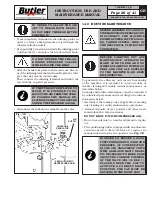
• The conditioning unit is equipped with an automatic
vacuum-operated drain therefore it requires no
manual intervention by the operator (see
Fig. 38
).
IN ORDER TO ENSURE A GOOD
FUNCTIONING AND TO AVOID THE
PRESENCE OF CONDENSATION
IN THE AIR TREATMENT UNITS
WITH SEMI-AUTOMATIC DRAIN,
IT'S NECESSARY TO MAKE SURE
ABOUT THE CORRECT POSITION
OF THE VALVE (FIG. 38 REF. 1),
PLACED UNDER THE CAP. TO
ACTIVATE A CORRECT DRAIN
FUNCTION, THE CAP MUST BE
ROTATED IN THE RIGHT WAY.
KARACTER.TLX - KARACTER.TLXFI
7108-M007-0_B

