Page 14 of 41
GB
INSTRUCTION, USE AND
MAINTENANCE MANUAL
KARACTER.TLX - KARACTER.TLXFI
7108-M007-0_B
11.2 Assembly procedures
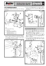
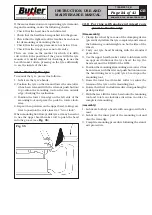
Assemble the machine with the help of the following
illustration.
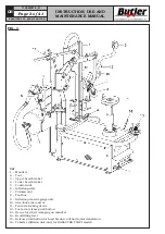
Fig. 6
KEY
1 – Grease holder ring
2 – Tool box
3 – Bracket for tank (only for
KARACTER.TLXFI model)
4 – Tank unit (only for
KARACTER.TLXFI model)
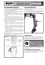
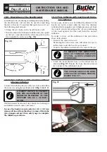
1- Mount the grease holding ring (# B0223000) (
Fig. 7
ref. 1
), in the accessory box, using the 2 provided
screws (
Fig. 7 ref. 2
) (# 203035), on the rivets
already present on machine body.
Fig. 7
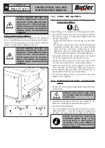
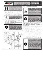
2. Fit the tool box (
Fig. 8 ref. 1
) to machine column,
using the 4 special screws provided (
Fig. 8 ref. 2
)
(# 272172).
Fig. 8
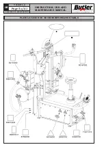
Only for KARACTER.TLXFI
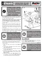
3. Fit the bracket for tank (
Fig. 9 ref. 1
) (# 710811600)
to the tool box (
Fig. 9 ref. 2
) using the 2 special
screws (
Fig. 9 ref. 3
) (# 201044) and the nuts
(
Fig. 9 ref. 4
) (# 228011), supplied.
Mount the tank unit (
Fig. 9 ref. 5
) to the bracket
for tank (
Fig. 9 ref. 1
) with the 4 screws (
Fig. 9
ref. 6
) (# 203019) and the nuts (
Fig. 9 ref. 7
) (#
228010), supplied.
4. Connect the black pipe (
Fig. 9 ref. 8
) and the blue
pipe (
Fig. 9 ref. 9
) on the provided quick couplings
as shown in figure
Fig. 9
.
Fig. 9


