INSTRUCTION, USE AND
MAINTENANCE MANUAL
GB
Page 33 of 67
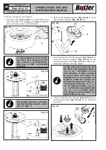
WHILE THIS OPERATION IS BEING
CARRIED OUT PAY ATTENTION
NOT TO DEFORM THE TYRE SIDE.
GREASE THE BEAD BEFORE THE
ROLL RE-ENTERS.
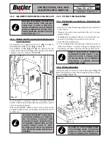
Fig. 33
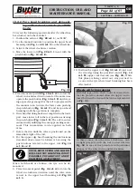
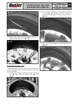
11. Move forward the tool so that it penetrates be-
tween the rim and the tyre (see
Fig. 34
). While
this operation is being effectuated, the tool rotates
around the rim edge until it hooks the tyre bead
(see
Fig. 35
).
Fig. 34
Fig. 35
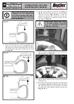
12. Lift the tool through the provided control (
Fig. 14
ref. H
). When the tool reaches a vertical position
related to the rim (
Fig. 36 ref. 1
), rotate the
mandrel so that the tyre enters the rim groove.
Keep on raising the tool until the bead is on the
rim edge (see
Fig. 35
).
MAKE SURE THAT THE TOOL
IS ON DEMOUNTING POSITION
(FIG. 35) BEFORE STARTING
MANDREL ROTATION.
Fig. 36
1
13. Rotate clockwise until the upper bead is completely
disassembled (see
Fig. 37
).
Fig. 37
14. Lift the upper tool in order to remove it from the
working area.
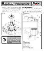
15. Move the tool forward through the provided lifting
control (
Fig. 14 ref. G
) until it is inserted between
rim edge and lower bead. Position the assembly
tool just next to the indicator reported on the tool
(
Fig. 38 ref. 1
).
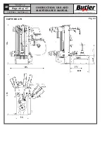
CAPTURE 4 - CAPTURE 4 FI
7104-M007-4_B

