INSTRUCTION, USE AND
MAINTENANCE MANUAL
GB
Page 30 of 67
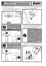
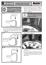
5 - Rotate clockwise the small internal levers (
Fig. 24A
ref. 1
), until they reach the outer levers (
Fig. 24A
ref. 2
) in order to unlock the ring-nut. Make the
rink-nut (
Fig. 24A ref. 3
) and the cone (
Fig. 24A
ref. 4
) approach the rim (
Fig. 24A ref. 5
). Release
the small inner levers (
Fig. 24A ref. 1
) the ring-nut
gets locked on the threaded shaft (
Fig. 24A ref. 6
).
Fig. 24A
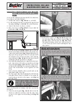
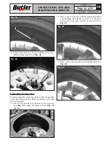
6 - Turn the ring nut (
Fig. 24B ref. 1
) clockwise
through the external levers (
Fig. 24B ref. 2
) until
the cone complete clamping (
Fig. 24B ref. 3
) on
the rim (
Fig. 24B ref. 4
).
Fig. 24B
7 - At the end of the operations, unlock the ring nut
by loosening first the cone with the external levers
and then moving the ring nut and the cone away
from the rim with the small levers.
Place the locking ring-nut onto its own activator
support.
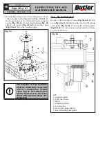
IN CASE THE PNEUMATIC SYS-
TEM FOR THE LIFTING OF THE
THREADED CENTRAL SHAFT
DOES NOT WORK (IN ORDER
TO CONTINUE WORKING UNTIL
THE REPAIR HAS BEEN CAR-
RIED OUT), LIFT MANUALLY THE
CENTRAL SHAFT
(
Fig. 25 ref. 1
)
UNTIL ITS MAXIMUM HEIGHT,
REMOVE THE PROTECTION CAP
(
Fig. 25 ref. 2
)
AND TIGHTEN THE
DOWEL
(
Fig. 25 ref. 3
)
TO LOCK
THE SHAFT INTO “COMPLETELY
LIFTED” POSITION.
WHEN THE REPAIR HAS BEEN
COMPLETED, SLACKEN THE
DOWEL TO RESET THE CORRECT
FUNCTIONING OF THE PNEU-
MATIC LIFTING DEVICE FOR THE
THREADED SHAFT.
Fig. 25
CAPTURE 4 - CAPTURE 4 FI
7104-M007-4_B

