INSTRUCTION, USE AND
MAINTENANCE MANUAL
GB
Page 32 of 67
13.3.2 Tyre bead breaking and demount-
ing with manual controls (in “MAN”
mode)
Carry out the following operations after the wheel has
been locked onto the mandrel:
1. Position the selector (
Fig. 28 ref. 1
) on “MAN”.
2. Use the manual controls to position the upper bead
breaking roll (
Fig. 1
and
2 ref. 3
) on the wheel rim.
3. Activate the wheel clockwise rotation.
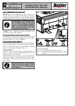
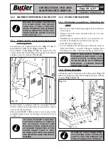
4. Move the lower roll (
Fig. 29 ref. 1
) near with the
push button (
Fig. 14 ref. E
).
1
Fig. 29
5. Press the assent pedal (
Fig. 16 ref. A
) to rotate the
wheel in clockwise direction and at the same time
operate the push button (
Fig. 14 ref. E
) until creat-
ing a space large enough for the roll to progress with
the manual cam. Activate the lower cam pushing
the push button (
Fig. 14 ref. C
) and keep on bead
breaking until the operation is complete.
6. Once bead breaking has been completed in the lower
part, move lower roll in the rest position activating
the push button (
Fig. 14 ref. E
). The roll re-enters
automatically nullifying the cam approaching move-
ment. This automatism can be applied on both
arms.
7. Rotate the rim until the valve is positioned on the
immediate right of the roll.
8. For the upper edge bead breaking the instructions
described above must be followed, but using the
push buttons related to the upper roll (
Fig. 14
ref. B
and
F
).
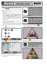
UNTIL BOTH UPPER AND LOWER
ROLLS DO NOT RE-ENTER, IS NOT
POSSIBLE TO CARRY OUT A NEW
DIAMETER ADJUSTMENT.
When both beads are broken, the tyre can be de-
mounted.
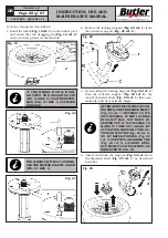
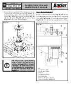
9. Press the assent pedal (
Fig. 16 ref. A
) to rotate the
wheel in clockwise direction until the valve stem
is next to the upper bead breaking roll (
Fig. 30
ref. 1
).
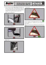
Fig. 30
1
2
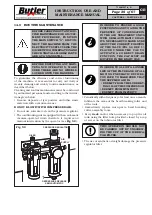
10. Position the upper tool (
Fig. 30 ref. 2
) just next
the rim edge using the provided control (
Fig. 14
ref. H
) (upper tool descent) (see
Fig. 32
). While
this phase is being carried out, stay just next to
a zone in the tyre where bead breaking has been
effectuated.
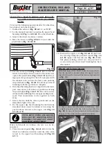
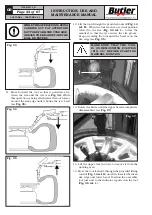
Wheels with rim protector
With this type of tire, there could be cases where
the rim protector doesn’t allow the upper tool to
insert between the rim and the tire (as represented
in
Fig. 31
).
Fig. 31
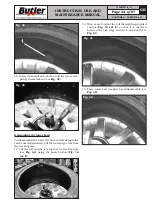
In these cases, turn the wheel clockwise, with
a slight pressure with the tool as described in
Fig. 32
. In case of rim protectors with particular
shapes, let the wheel turn counter-clockwise.
Fig. 32
CAPTURE 4 - CAPTURE 4 FI
7104-M007-4_B

