INSTRUCTION, USE AND
MAINTENANCE MANUAL
GB
Page 36 of 67
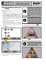
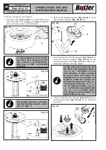
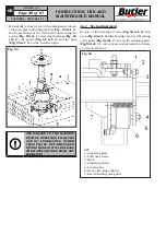
7. Lower the upper bead breaker roll so that the tyre
bead is kept at the same height of the rim groove
(see
Fig. 48
).
Fig. 48
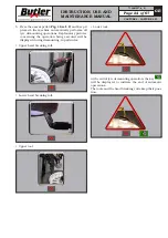
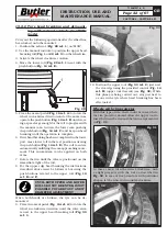
8. Rotate clockwise until tyre complete assembly (see
Fig. 49
).
FOR THE MOUNTING OF VERY
DIFFICULT WHEELS, USE THE EX-
TENSION OF THE BEAD DEPRES-
SOR (FIG. 49 REF. 1) (OPTIONAL).
Fig. 49
1
9. When the operations have been completed move all
the tools in rest position.
13.5 "Special use of bead breaker in “AUTO
mode without PC management”
Follow the operations described in paragraph
“11.3
Machine use in “AUTO” mode without PC manage-
ment”
to diametrically position the tools/bead break-
ing rolls onto the rim base.
In addition to its use during mounting and demounting,
the bead-breaker roll can also be used for matching
the tyre to the rim. To conduct this operation carry out
the following instructions.
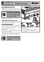
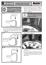
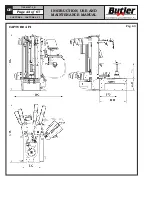
• Clamp the tyre between the bead breaker roll.
• Turn the motor clockwise until the reference point
on the tyre coincides with the reference point on the
rim (usually the valve) (see
Fig. 50
).
At the end of the operations, the machine has stored the
sizes (width and rim diameter) of the lastly used wheel.
When this mode is left (press “ESC” key), the sizes of
the used wheel are not stored in the memory bank,
therefore, they can not be used for the following op-
erations.
13.6 Special use of the bead-breaker (only
in “MAN” mode)
In addition to its use during mounting and demounting,
the bead-breaker roll can also be used for matching
the tyre to the rim. To conduct this operation carry out
the following instructions.
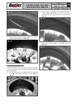
• Clamp the tyre between the bead breaker roll.
• Turn the motor clockwise until the reference point
on the tyre coincides with the reference point on the
rim (usually the valve) (see
Fig. 50
).
Fig. 50
CAPTURE 4 - CAPTURE 4 FI
7104-M007-4_B


