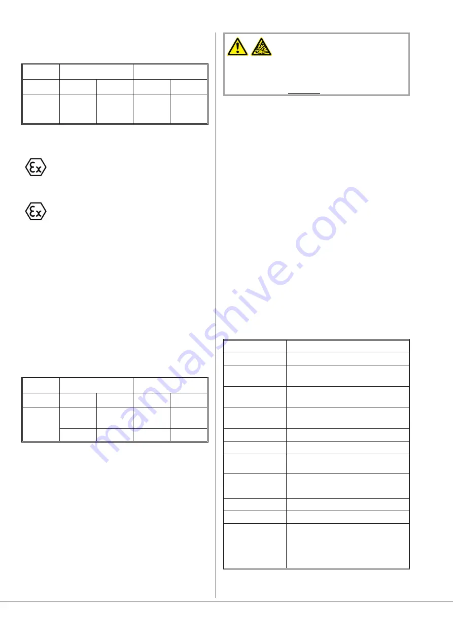
In the table below, you will find the possible alternative of temperature
classes depending of the cooling system and the maximal motor
frequency:
Cooling
system
Direct cooling
Recirculating cooling
Type
Temperature
class
Max. motor
frequency
Temperature
class
Max. motor
frequency
NC 0200 B
T4(i/o)
T3(i)/T4(o)
T3(i/o)
50 Hz
60 Hz
60 Hz
T3(i/o)
T3(i)/T4(o)
60 Hz
60 Hz
COBRA NC 0300 B
or
The following temperature classes are available
–
T4(i/o)
or
–
T3(i/o)
when the vacuum pump is equipped with a direct cooling system.
The
internal and external temperature class must be identical !
If the va-
cuum pump is equipped with a recirculating cooling system, only the
temperature class
T3(i/o)
is available.
For the adjustment of the temperature class, imperatively refer to
“Adjustment of the thermostatic valve (option) and adjustment of the
temperature class”.
In the table below, you will find the possible alternative of temperature
classes depending of the cooling system and the maximal motor
frequency:
Cooling sys-
tem
Direct cooling
Recirculating cooling
Type
Temperature
class
Max. motor
frequency
Temperature
class
Max. motor
frequency
NC 0300 B
T4(i/o)
T3(i/o)
50 Hz
50 Hz
T3(i/o)
50 Hz
T3(i/o)
60 Hz
Installation
Vacuum system
The vacuum system must be placed in a horizontal position on a level
surface.
Make sure there is enough space around the pump system (at least
1.5 m) for service work, etc.
The pipes must be cleaned before assembly. Be sure to completely re-
move any foreign matters such as welding slag and swarf. Flush or
blow out the pipes before connecting up.
Install the inlet pipe (into the nominal diameter of the pump flange or
the inlet valve port) as short as possible because of resistance in the pi-
peline. If longer pipelines (> 5 m) are planned, a wider nominal diame-
ter is necessary.
Connect the pipes in such a way so that no tensile or compressive
stress is placed on the system, using bellows if necessary.
WARNING
A filter or a screen has to be installed on the suction side of the va-
cuum pump, in order to avoid any suction of particles and foreign
matter in the vacuum pump (explosion danger ! ).
The filter or the screen should have a mesh size
£
0.8mm.
Busch offers an intermediate flange screen, which corresponds to this
prescription (for DN50 flange: Busch Part No. 0534 538 534)
The inlet and outlet pipes must be laid with gradients so that no
condensation can enter the pump.
Electrical connection/ Checks
Electrical installation may only be carried out by a specialist.
l
Make sure that the requirements according to EMC-Directive
2014/30/EU as well as the current EN-standards, electrical and
occupational safety directives and the local or national regulations
respectively, are complied with (this is the responsibility of the
designer of the machinery into which the vacuum pump is to be
incorporated; see also the corresponding comments in the
E
U-
Declaration of Conformity).
l
Make sure that the power supply is compatible with the data on
the nameplate of the drive motor
l
Make sure that an overload protection according to EN 60204-1 is
provided for the drive motor
l
Make sure that the drive of the vacuum pump will not be affected
by electric or electromagnetic interference; if unsure please seek
advice from your Busch representative
If the direction of rotation of the pump is wrong, serious damage may
occur.
In order to change the direction of rotation, two phases on the motor
must be reversed.
If the vacuum pump is delivered without drive motor, a drive motor
must be mounted according to the following specifications:
Motor type
3ph motor - synchronous motor
Number of poles
2
Size
COBRA NC 0100 B
BG 100
Size
COBRA NC 0200 B
BG 132
Size
COBRA NC 0300 B
BG 132
BG 160 with adapter flange
Fixing type
Flange, IM 3001 (IM B5)
Assembly position
Shaft horizontal
Network frequency
max. 50 Hz, resp. 60 Hz. See nameplate of the
vacuum pump
Varaible speed drive
Authorized for all vacuum pumps.
The motor must be of nominal constant power
over the entire speed range.
Network voltage
Customised
Protection type
Customised
Explosion protection
In regard to its explosion protection, the motor
must have at least the same protection level as
the vacuum pump for the outside area (“outside”
(o)). See nameplate of the vacuum pump. A
higher protection level, e.g. for the explosion
group or the temperature class, can also be used.
The highest permissible motor power is regulated according to the
operating frequency and the operational mode, see table below:
Installation
Seite/ Page/ Page 16
2G
or
3G
IIB
T3, T4*
No ATEX Zone
2G
or
3G
IIB
2G
or
3G
IIC
or
IIB
II
I
nside
O
utside
II
I
nside
Ex
h
Ex
h
Ex
h
T3,
T4*
T3, T4*
Gb
or
Gc
Gb
or
Gc
X
X
or
Gc
X
O
utside
II
II
Gb


