


Page 38
SERVICE (cont.)
DIGITAL TIMER (Late Models)
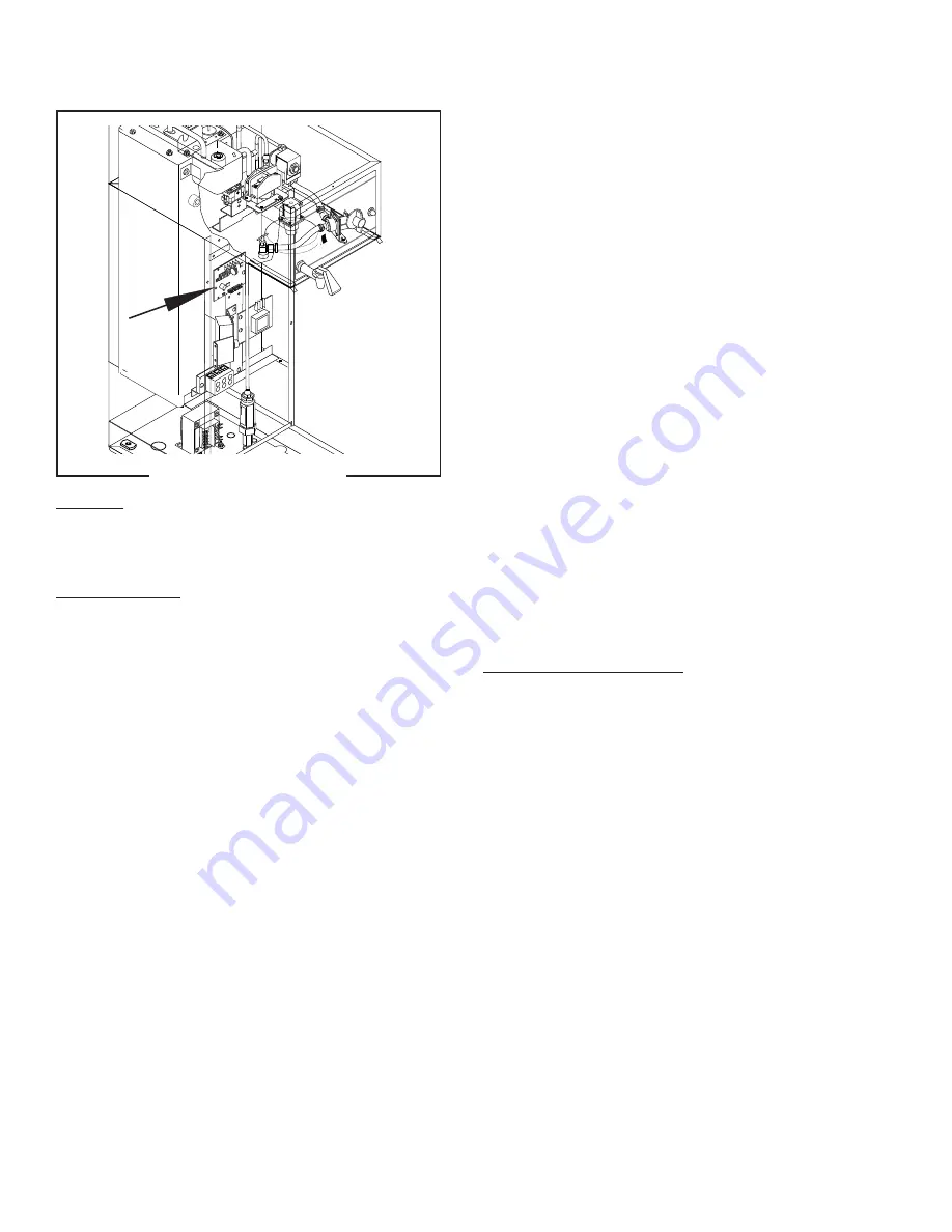
Location:
The timer is located inside the left front of the
brewer on the upper part of the component bracket.
Test Procedures:
NOTE:
Do not remove or install wires while timer board
is installed. Pressure applied to one side may cause
damage to the board.
1. Disconnect the brewer from the power source and
remove the front access panel.
2. Remove the two #8-32 screws securing circuit
board to the mounting bracket.
3. Remove circuit board and spacers (as required).
4. With a voltmeter, check the voltage across termi-
nals TL1 and TL2 when the "ON/OFF" switch is in
the "ON" position. Connect the brewer to the power
source. The indication must be:
a) 120 volts ac for two wire 120 volt models and
three wire 120/240 volt models.
b) 200 to 240 volts ac on two wire 200 volt or 240
volt models.
5. Disconnect the brewer from the power source.
If voltage is present as described, proceed to #6.
If voltage is not present as described, refer to the
Wiring Diagrams and check the brewer wiring har-
ness.
TL5
TL4
TL3
TL2
TL1
J2
J1
SE
T
LO
CK
LOCK
SET
1
2
3
4
5
6
1 2 3 4 5 6
BUNN
90 psig max operating pressure
Strainer/Flow Control # 22300.033 0
(Repl. Flow Washer #20526.0330)
(Repl. Screen #23721.0000)
.500 gpm FLOW
FIG. 38 DIGITAL TIMER
P2230
28230 031201
6. With a voltmeter, check the voltage across termi-
nals TL1 and TL4 when the "ON/OFF" switch is in
the "ON" position. Connect the brewer to the power
source. The indication must be 0 volts.
If voltage is as described, proceed to #7.
If voltage is not as described, disconnect the brewer
from the power source and replace the timer.
7. With a voltmeter, check the voltage across termi-
nals TL1 and TL4 when the "ON/OFF" switch is in
the "ON" position. Connect the brewer to the power
source and press the "START" switch. The indica-
tion must be as follows:
a) 120 volts ac for two wire 120 volt models and
three wire 120/240 volt models.
b) 200 to 240 volts ac on two wire 200 volt or 240
volt models.
If voltage is present as described, the brew timer is
operating properly. Reset the timer as required, to
obtain the desired brew volume.
If voltage is not present as described, disconnect the
brewer from the power source and replace the timer.
Removal and Replacement:
NOTE:
Do not remove or install wires while timer board
is installed. Pressure applied to one side may cause
damage to the board.
1. Remove the four #6-32 screws securing circuit
board to component mounting bracket.
2. Remove circuit board and nylon spacers.
3. Remove all wires from the timer.
4. Attach all wires to the replacement timer board
prior to installation to the component mounting
bracket. Refer to FIG. 39 when reconnecting the
wires.
5. Install new circuit board with nylon spacers to
component mounting bracket using two #6-32
screws.
6. Adjust the timer as described below.


