Buller Enterprises Panel Pro 6126 Operation & Maintenance Instructions Manual Download Page 38

38

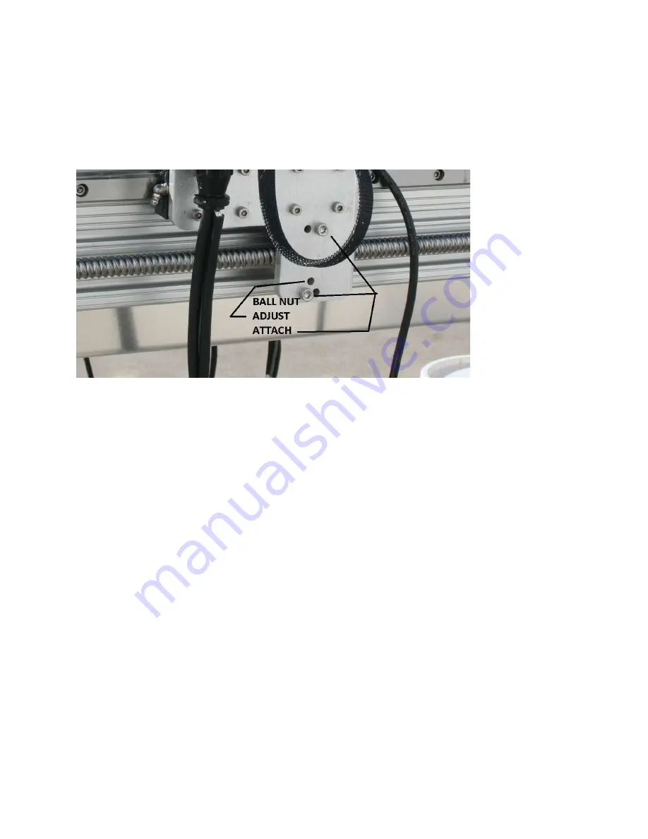
backlash, a clunking sound will be heard.  Make sure the ball nut mount screws are 
tight.  The adjust screw is located between the mount screws and uses a 3mm Allen 
wrench. Tighten slightly until clunking sound disappears.  Traverse the axis end to end 
and listen for any unusual sounds or binding.  Some areas of the lead screw may be 
slightly tighter than others.  The ball nut needs to be adjusted for the tightest location.   
The picture shows the X2 axis, but the X1 axis and Y axis have a similar arrangement.

Caution! Over tightening the ball nut adjusting screw will destroy the ball nut

ADJUST LEAD SCREW BACKLASH:

This adjustment preloads the lead screw bearings.

The Panel Pro 6126  X and Y axis are similar. They use a double bearing at the motor 
end and a floating bearing at the knob end.  The knob end has two Bellville washers 
that the knob tightens against with the screw in the middle of the knob.  This eliminates 
backlash with constant preload on the bearings.  The pointed end of the Bellville 
washers should oppose each other, one end pointed to the flange bearing, and the 
other to the knob.

Hold the lead screw (on the screw part, not the smooth machined part) with pliers near 
nut end. Loosen the ¼ x 20 stop nut from the knob.
The knob is threaded.  The knob should be tightened about ¼ to 3/8 of a turn beyond 
the point where the knob contacts the belleville washers.
Tighten the jamnut make sure the knob to ballscrew position does not shift while 
tightening the jam nut

STORAGE

Make a habit of covering the Panel Pro after use.  Keep the ways clean and oiled with 
LPS2.  For long term storage coat the steel parts with a preservative oil like LPS3.

Summary of Contents for Panel Pro 6126

Page 1: ...1 Panel Pro MODEL 6126 SN 3001 and subsequent OPERATION AND MAINTENANCE INSTRUCTIONS copyright 2021 Buller Enterprises Inc...

Page 2: ...cription of Panel Pro 6126 3 Set Up Panel Pro Hardware Setup 5 Software Setup 12 Try it out 14 Manual movement with keys and mouse 17 Cutting Files 18 QCAD 23 Troubleshooting 33 Maintenance 36 3 axis...

Page 3: ...shapes such as instrument cutouts can be drawn and stored for subsequent combination into various instrument panels The machine is also useful to fabricate various adapters and brackets that have many...

Page 4: ...power cord X axis YZ axis controller cables and USB cable 10 Tool kit with various tools starter supply of end mills etc 11 Software AvCAM QCAD and Drawing Library inside the 3 ring binder 12 Optiona...

Page 5: ...tial that there is the same ground on both the Panel Pro and the computer The Bosch router draws around 12 amps at turn on If extension cords are used or other loads on the circuit cause the voltage t...

Page 6: ...the drain pan and have one person support it in that position while the other attaches the legs DO NOT APPLY PRESSURE TO THE LEAD SCREW LEAD SCREW SUPPORTS or LEAD SCREW GUARDS 8 Level the machine by...

Page 7: ...screws and then tighten the coupler clamp 12 After both X1 and X2 motors are installed and the couplers tight move to the left side of the machine and grasp the 2 knobs Turn counter clockwise until th...

Page 8: ...the hose adapter found in the same package as the hose with the hose pointing up Place the pump in the pail with pump inlet on the bottom Place the pump and tank on the floor with the large hole posit...

Page 9: ...3 4 months or sooner Plan to clean the chips out of the drain pan every day The chips may be scraped uphill in the drain pan to facilitate draining 17 You will find the 2 pieces of the flow director...

Page 10: ...onnector for the X axis limit switch and a 2 pin connector for a laser warning light 21 Locate the nuts with screws installed on the bottom of the right rail Allow enough room to comfortably attach th...

Page 11: ...er housing Snug the clamp screws equally Don t over tighten 26 The bottom 43mm clamp accessory mount is used for the engraver and other accessories The lower clamp tightening screw may be removed for...

Page 12: ...o recommend 8GB memory If a computer is used that has been used for other purposes clear out any unused programs The only programs you should have open is AvCAM and QCAD or other cad program The keybo...

Page 13: ...Start run E QCAD autorun bat where E is your usb drive number This batch file installs AvCAM sets up the proper folders and copies the drawing libraries Note the application key on the thumb drive en...

Page 14: ...lights up To turn it off push the off button below the pilot light Pressing the emergency shut off or the red momentary switch will depower all drive and spindle operation The interlock jumper plug mu...

Page 15: ...repair the leak Make sure any area where power cords run are dry Under no circumstances should the guard around the router bit be removed while the router is running Coolant and metal chips will fly...

Page 16: ...elp file is the main operating manual for the Panel Pro If the help file is not found navigate to the folder where AvCAM is located if prompted and locate AC19 chm After the machine is set up and comm...

Page 17: ...m travel down of about 3 125 inches When at any position hold the 3 key to move move it down at a slow rate until it reaches the soft limit The 9 key raises it all the way to the top normally at the p...

Page 18: ...ates Hit F1 on any dialog for help with that dialog Cutting a drawing We ll start our discussion by routing a single instrument hole For instance an altimeter drawing is an individual shape its refere...

Page 19: ...8 end mill with a 3 16 shank and a 250 length of cut for the normal cuts on 062 and thicker material If you need to make 3 32 holes for nut plates put those holes on a separate layer and cut those ho...

Page 20: ...bubbles in the clear coolant hose When bubbles appear dump about a gallon of water into the drain pan Clean parts with clear water to remove residual coolant Dried coolant leaves a sticky film At a m...

Page 21: ...the back needs to be plugged in for the power to come on The connector provides provisions for a customer supplied guarding system and will shut down the machine when open Spindle The 1 position allo...

Page 22: ...you can also switch the SC3 spindle switch to 0 This is good for repositioning clamps When ready to continue turn the spindle switch back on then hit enter to resume motion In the case of a broken bi...

Page 23: ...e extensions for known file types Click OK QCAD Installation A single user QCAD license is provided for you using the data and email supplied by you The current version of QCAD is supplied on the USB...

Page 24: ...opy QCAD ini to users your user name appdata roaming copy PanelPro dxf from the USB drive to Programfiles QCAD libraries templates Now open QCAD There are two types of items to display on the main scr...

Page 25: ...lections Toolbars are similarly selected and the recommended toolbars are shown to the right Menu Edit Drawing preferences Drawing unit should be set to Inch AvCAM 18 and 19 can convert metric to inch...

Page 26: ...26 The PanelProTemplate DXF template file is available at www bullerent com downloads and on the USB drive Copy it and save it to the folder listed above...

Page 27: ...ou want it to show Menu is the main menu at the top of the screen Tool Bar is the main tool bar at the top of the screen CAD Tool Bar is the Tool bar at the left of the screen where you select the ent...

Page 28: ...ave multiple drawings open They can be selected by the tab bar or on the window menu When all of your changes have been made click ok Close and re open QCAD The plan of attack The most efficient way t...

Page 29: ...of a house drawing would have the foundation drawn another layer would have basement rooms another layer could have main floor rooms another layer the wiring etc Now if all of this information would...

Page 30: ...ent A handy feature is the hide all grayed out eye on the top and show all the Black eye on the top buttons which hide all of the layers except the current layer and show all of course un hides them F...

Page 31: ...ine Now draw vertical lines on your paper that are parallel with the left side line Make the distances easy to measure like 3 75 What we are trying to accomplish is to generate the curve by defining c...

Page 32: ...with a caliper at 1 5 Then measure from the lower edge of the panel to the lower edge of the hole and find that it is 2 188 2 188 the yoke hole diameter 75 is 2 938 the vertical coordinate of the hol...

Page 33: ...g material that is too thick Any thing thicker than 125 aluminum should be cut with multiple passes not exceeding 125 per pass removing chips from the slots between passes A good coolant flow will hel...

Page 34: ...single flute end mill we suggest the our EM125 2 Never use a 4 flute end mill on aluminum Use sharp end mill Make sure there are no loose components on the machine such as the Z axis bearings Use hold...

Page 35: ...hile homing to see if both are running Mis alignment from one hole to another The Panel Pro has lost steps Check that panel is mounted so that full travel can be achieved If the X or Y axis hits a sto...

Page 36: ...e coupler above can work loose If that is the case the coupler must be disassembled tightened and reinstalled MAINTAINING THE PANEL PRO PREVENTATIVE MAINTENANCE After cutting wipe the ways linear bear...

Page 37: ...move the x1 and x2 lead screws using the knobs on the left end of the machine simultaneously until both touch their stops The stop is a 6mm dog point blunt set screw that is Lock Tited into the Motor...

Page 38: ...le bearing at the motor end and a floating bearing at the knob end The knob end has two Bellville washers that the knob tightens against with the screw in the middle of the knob This eliminates backla...

Page 39: ...n AvCAM commands a Z down to cut depth it will travel at the currently selected rapid traverse speed to zero and then at the cutting speed to cut depth What ever tool you are using will need to have a...

Page 40: ...e tip of the tool will be above zero Be aware that the Z Zero will change for each tool and each change in material thickness The tool installed in the picture is a 100 degree countersink It can be us...

Page 41: ...t in this operation Set the operating mode I E auto tool path Set the end mill diameter in the cut dialog Simulate the file Install the tool on the router Set the x y zero This only needs to be done o...

Reviews: