


VIBROCONTROL 1500
Connections
- 24 -
VC1500EN / C103845.002 / V 09 / 14.04.2015
5.4
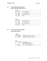
Connection terminal layout -
power supply AC-4111
L
mains L
N
mains N
+
+24 V power supply for VIBROCONTROL 1500
-
0 V power supply for VIBROCONTROL 1500
Refere chapter 10.1. for more details.
5.5
Sensor connection and sensor monitoring
VIBROCONTROL 1500 is prepared for connection of two acceleration
sensors with constant-current power requirement (CCS type) and an output
sensitivity of 100 mV/g.
When connecting the sensors it must be noted that a connection between
SIG- and GND as well as between SIG+ and POWER must be made.
For testing the error-free function of the sensor a test voltage is measured
between SIG+ and SIG-. The permissible voltage range lies between 8 – 16
V + 0.5 V.
If the test voltage at both channels lies outside of this range the OK relay
switches and error-message 10 ”Both ch sensors“ appears in the display.
In a case where the test voltage at only one channel lies outside the
permissible range, the OK relay will switch and the message "Sensor error"
appears (sensor fault) with a display of the relevant channel. Other functions
of the instrument are normal.
In an error case the current output of the channel will go back to 2mA output
current.
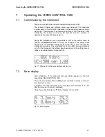
Fig. 8: Display of sensor fault in channel B