-14-
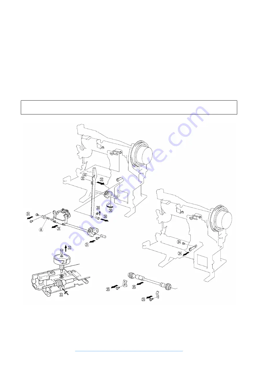
30. Remove the lock ring for the horizontal feed arm shaft, loosen the horizontal feed arm set screw, then
remove the horizontal feed arm shaft.
31. Remove the screws holding the horizontal feed assembly center right and the horizontal feed assembly
center left, remove the horizontal feed assembly center right and the horizontal feed assembly center left,
then remove the horizontal feed shaft assembly.
32. Remove the forked connecting rod.
33. Loosen the rotary hook shaft set screw, then remove the rotary hook assembly, rotary hook shaft, and three
washers.
34. Remove the screw holding the tension pulley assembly, then remove the tension pulley assembly.
35. Remove the screw holding the eccentric metal presser and the screw holding the lower shaft metal presser,
then remove the lower shaft assembly.
Disassembly Point
31. Be careful not to lose the pressure spring (A) in the horizontal feed assembly center left.
www.promelectroavtomat.ru
Summary of Contents for XL-6040
Page 1: ... 6 2001 www promelectroavtomat ru ...
Page 3: ... 1 I 1 MECHANICAL CHART 2 2 POWER TRANSMISSION CHART 3 www promelectroavtomat ru ...
Page 4: ... 2 1 MECHANICAL CHART www promelectroavtomat ru ...
Page 29: ... 27 2 LEAD WIRES ARRANGEMENT www promelectroavtomat ru ...
Page 61: ...XL 6060 Series XL 6050 Series XL 6040 Series H1040194 www promelectroavtomat ru ...


