-9-
8.
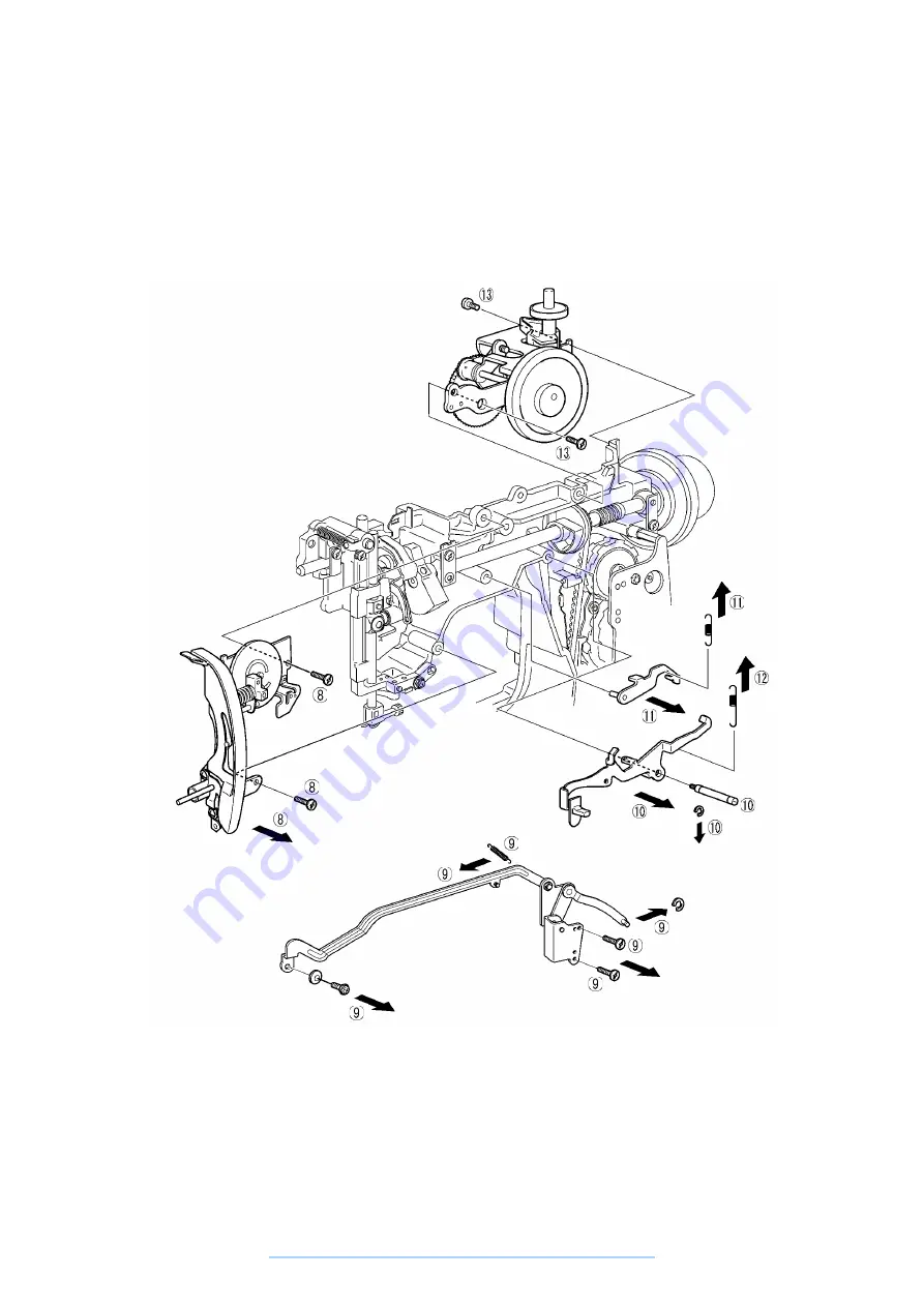
Remove the two screws holding the thread tension assembly, then remove the thread tension assembly.
9.
Remove the two screws, the lock ring, and the feed rod tension spring, remove the tightening screw for the
Zigzag adjustment nut for the Zigzag connecting rod, then remove the Zigzag connecting rod assembly.
10. Remove the lock ring, and the screw, then remove reverse sewing lever A.
11. Remove the tension spring for reverse sewing lever B, then remove reverse sewing lever B.
12. Remove the feed regulator tension spring.
13. Remove the two screws holding the feed bracket assembly, then remove the feed bracket assembly.
www.promelectroavtomat.ru
Summary of Contents for XL-6040
Page 1: ... 6 2001 www promelectroavtomat ru ...
Page 3: ... 1 I 1 MECHANICAL CHART 2 2 POWER TRANSMISSION CHART 3 www promelectroavtomat ru ...
Page 4: ... 2 1 MECHANICAL CHART www promelectroavtomat ru ...
Page 29: ... 27 2 LEAD WIRES ARRANGEMENT www promelectroavtomat ru ...
Page 61: ...XL 6060 Series XL 6050 Series XL 6040 Series H1040194 www promelectroavtomat ru ...


