-20-
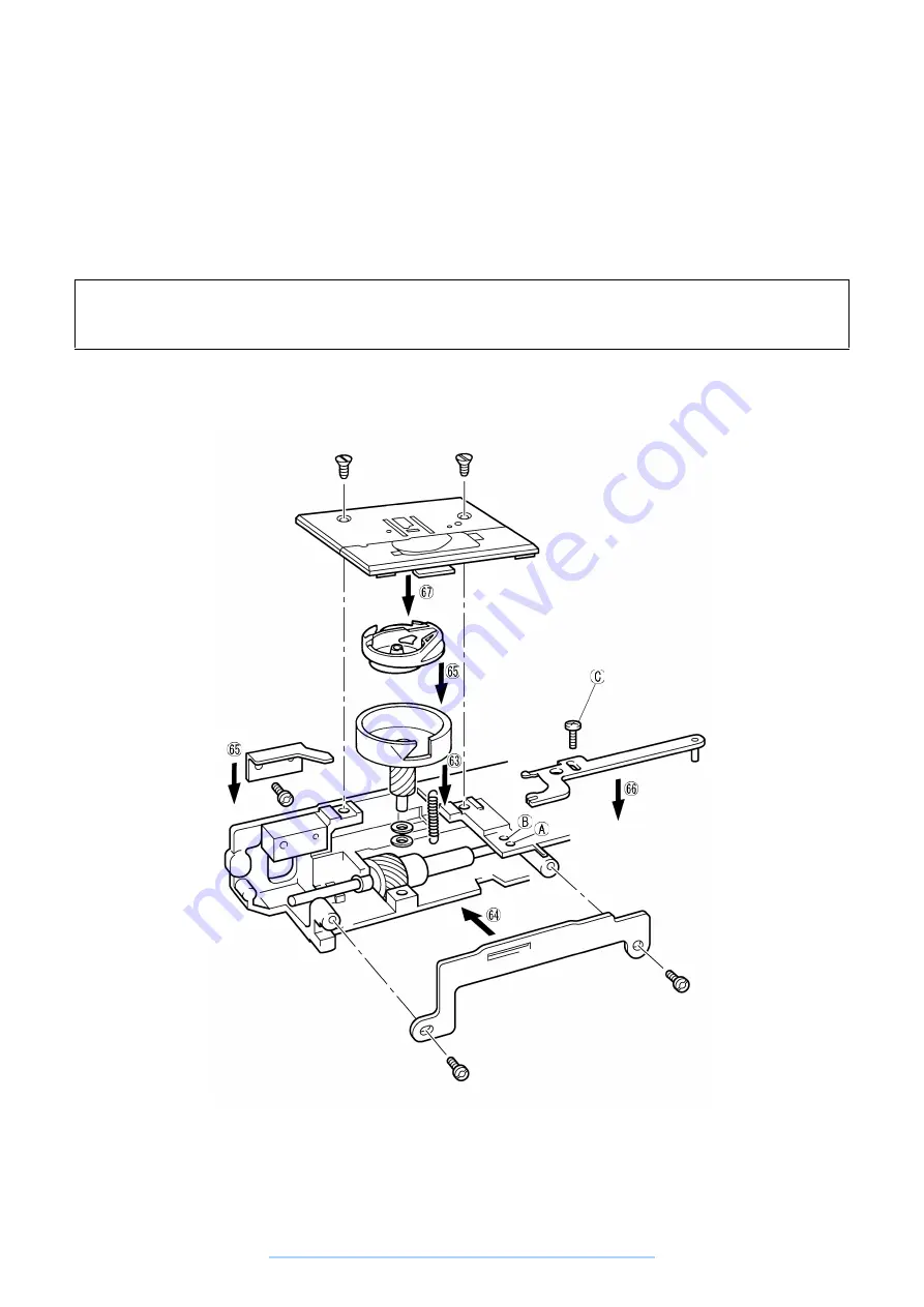
63. Hang the feed base tension spring.
64. Install the camber prevention plate with the two screws.
65. Put the inner rotary hook in place and install the inner rotary hook left retainer plate with the screw.
(See Adjustment Procedure 9.)
66. Install the inner rotary hook rotation prevention bracket with the screw. (See Adjustment Procedure 10.)
67. Install the needle plate assembly with the screw and check the feed teeth left-right position.
(See Adjustment Procedure 11.)
Assembly Point
66. Screw the inner rotary hook rotation prevention bracket screw (C) into screw hole (A), not (B). If you
screw it into (B), it will not be possible to install the needle plate assembly correctly.
www.promelectroavtomat.ru
Summary of Contents for XL-6040
Page 1: ... 6 2001 www promelectroavtomat ru ...
Page 3: ... 1 I 1 MECHANICAL CHART 2 2 POWER TRANSMISSION CHART 3 www promelectroavtomat ru ...
Page 4: ... 2 1 MECHANICAL CHART www promelectroavtomat ru ...
Page 29: ... 27 2 LEAD WIRES ARRANGEMENT www promelectroavtomat ru ...
Page 61: ...XL 6060 Series XL 6050 Series XL 6040 Series H1040194 www promelectroavtomat ru ...


