


-21-
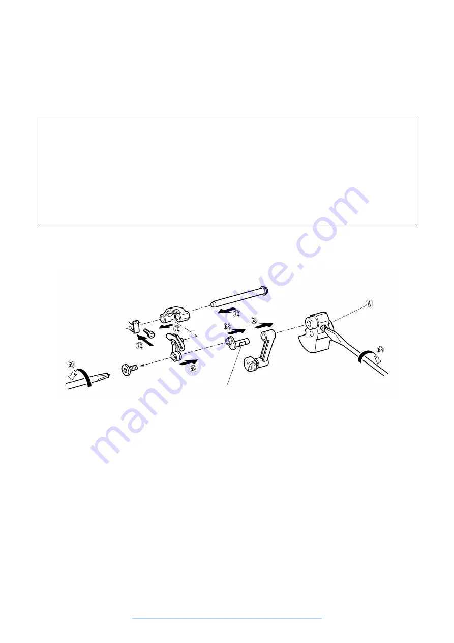
68. Put the needle bar crank rod onto the needle bar crank shaft and install on the thread take-up crank with the
set screw. Be careful about the flat surface the screw contacts with.
69. Install the thread take-up lever on the needle bar crank with the left screw.
70. Insert the thread take-up lever support between the thread take-up lever and the thread take-up lever shaft
and install the thread take-up lever shaft with the fastening plate and the screw.
Assembly Points
68. Check that the needle bar crank rod has no axial play.
Check that the needle bar crank rod rotates freely.
68. Fasten with the contact surface (flat surface) of the needle bar crank rod screw at the screw (A) side.
When installing the screw (A), hold the balance wheel by hand so that the upper shaft does not rotate.
69. Hold the balance wheel by hand so that the upper shaft does not rotate ad rotate the driver to the left to
tighten the thread take-up lever left screw.
70. Install so that there is no clearance between the thread take-up lever support right side surface and the
lock ring. If there is a large clearance, left-right play of the thread take-up lever will generate abnormal
noise (thread take-up lever rattling). Also, turn the upper shaft by hand and check that rotates freely.
Flat surface
www.promelectroavtomat.ru
Summary of Contents for XL-6040
Page 1: ... 6 2001 www promelectroavtomat ru ...
Page 3: ... 1 I 1 MECHANICAL CHART 2 2 POWER TRANSMISSION CHART 3 www promelectroavtomat ru ...
Page 4: ... 2 1 MECHANICAL CHART www promelectroavtomat ru ...
Page 29: ... 27 2 LEAD WIRES ARRANGEMENT www promelectroavtomat ru ...
Page 61: ...XL 6060 Series XL 6050 Series XL 6040 Series H1040194 www promelectroavtomat ru ...


