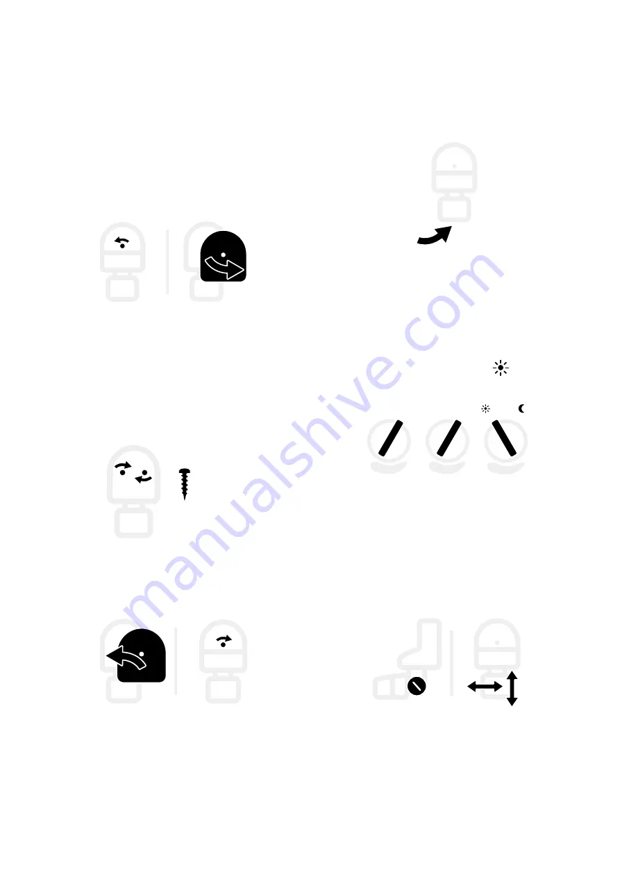
background image

82   |   

Add a motion sensor

   Deploy motion sensor  

C | Adjust setting dials

1.  Find the setting dials on the 

bottom of the sensor. 

2.  Set the dials as follows:


> Set 

SENS

 to minimum 

-

.


> Set 

TIME

 to minimum 

-

.


> Set 

LUX

 to maximum 

D | Aim sensor

•  Aim the sensor. 

Loosen the side knob to adjust. 

Sensor range is 180° .

LUX

+ TIME -

+ SENS -

•  Allow for a discreet cable run to 

the Rapid Deploy.

B | Mount sensor

1.  Remove the cover. 

Loosen the screw to remove the 
cover. 

2.  Place the sensor in position.

3.  Secure with two #12, 316 stainless 

steel screws . 

Match the screw to the surface 
material. 

4.  Reattach the cover and secure 

with screw. 

2x

Summary of Contents for Rapid Deploy

Page 1: ...Setup Guide BRNKL Rapid Deploy RSG1002021 ...

Page 2: ...Get more help at brnkl io help ...

Page 3: ...Before you start 1 Before you start Caution If you re unfamiliar with basic electrical systems hire a professional installer or a marine electrician ...

Page 4: ...you need 8 Connect to mobile network 9 Add to fleet 11 Rename BRNKL 12 Ready devices 13 Set up monitoring and alerts 14 Arm and disconnect 17 Deploy 20 What to bring 21 Install Rapid Deploy 22 Add solar panel 23 Add antenna 27 Deploy devices 30 Set and calibrate 31 Recover 34 What to bring 35 Take down 36 Reset 40 ...

Page 5: ...ensor 63 Ready door sensor 64 Deploy door sensor 66 Add a pressure mat 71 Ready pressure mat 72 Deploy pressure mat 74 Add a motion sensor 78 Ready motion sensor 79 Deploy motion sensor 81 Add a camera 86 Ready camera 87 Deploy camera 92 Reference 97 Rapid Deploy connections 98 Rapid Deploy default settings 99 Device settings 104 Rapid Deploy shopping list 107 Legal 108 ...

Page 6: ...4 Meet Rapid Deploy Meet Rapid Deploy A B D E C Connection panel Switch panel Solar charge controller A B Information label BRNKL C D E ...

Page 7: ...Antenna Know location and stay connected when deployed within mobile network coverage Solar panel Power your Rapid Deploy Float switch Know when a water level changes Door sensor Know when a door opens or closes Pressure mat Know when an intruder enters Motion sensor Know when an intruder enters Satellite device Stay connected when deployed outside mobile network coverage Camera Take and view phot...

Page 8: ...6 Setting up Rapid Deploy Setting up Rapid Deploy Set up your BRNKL Rapid Deploy by following these steps Get ready to deploy Deploy Deploy in the field Take down and reset Ready Recover ...

Page 9: ...L Rapid Deploy ready before you go into the field Follow these steps What you need Connect to mobile network Add to fleet Rename BRNKL Ready devices Set up monitoring and alerts Arm and disconnect Mobile network coverage required ...

Page 10: ...ices BRNKL Rapid Deploy serial number and password GPS Mobile Antenna You may need RockBLOCK satellite device compatible cable BRNKL Camera Mobile Device iOS or Android mobile device connected to internet BRNKL app installed Services BRNKL user account and password BRNKL Rapid Deploy service subscription ...

Page 11: ... connect Rapid Deploy to the mobile network follow these steps Connect LTE antenna Turn on battery Connect LTE antenna Connect your BRNKL Rapid Deploy to mobile networks To connect LTE cable On the connection panel 1 Plug the LTE antenna cable into the CELL port 2 Turn the collar to fasten CELL LTE ...

Page 12: ...10 Ready Connect to mobile network Turn on battery Power your BRNKL Rapid Deploy To turn on the battery Inside the Rapid Deploy 1 Find the switch panel 2 On the panel switch BATTERY to ON BATTERY ON OFF ...

Page 13: ...dded to fleet BRNKL displays the added BRNKL Fleet Added Name Add to fleet Manage your BRNKL from the BRNKL app To add a BRNKL to your fleet On your mobile device or browser 1 Open BRNKL 2 Do one of the following From Fleet view select From Map Graphs Photos or Alerts go to the status bar and select the BRNKL name Fleet Name ...

Page 14: ...ve Rename BRNKL Name your BRNKL so you know what it s monitoring To rename BRNKL On your mobile device or browser 1 Open BRNKL 2 From Settings select BRNKL then go to BRNKL settings 3 In Name enter a new name BRNKL BRNKL BRNKL Name Enter name ...

Page 15: ...oy ready for any devices you plan to add to your setup To ready your Rapid Deploy for devices Follow the instructions for the type of device Satellite device page 44 Float switch page 57 Door sensor page 64 Pressure mat page 72 Motion sensor page 79 Camera page 87 ...

Page 16: ...about To set monitoring and alerts follow these steps Set up device monitoring Set up device alerts Set up device monitoring Set which devices BRNKL monitors To send alerts BRNKL needs to monitor the device To set up device monitoring On your mobile device or browser 1 Open BRNKL 2 From Settings select Devices Devices ...

Page 17: ...onitor Save Set up device alerts Set which devices BRNKL sends alerts about To send alerts BRNKL needs to monitor the device To set up device alerts On your mobile device or browser 1 Open BRNKL 2 From Settings select Devices 3 In the settings for each monitored device do one of the following To send alerts about the device turn on Alert To stop alerts about the device turn off Alert Device Alert ...

Page 18: ...16 Ready Set up monitoring and alerts 4 Save settings Save ...

Page 19: ...battery Disconnect LTE antenna Rapid Deploy must be armed before you deploy outside mobile network coverage Arm BRNKL Set BRNKL to send alerts when something happens To arm BRNKL On your mobile device or browser 1 Open BRNKL 2 From Map Graphs Photos or Alerts go to the status bar 3 Check the status indicator then do one of the following If status is Armed do nothing BRNKL is armed Armed ...

Page 20: ...isarmed select the status indicator to arm Unarmed Turn off battery Conserve your BRNKL Rapid Deploy battery when not in use To turn off battery Inside the Rapid Deploy 1 Find the switch panel 2 On the panel switch BATTERY to OFF BATTERY ON OFF ...

Page 21: ... LTE antenna Disconnect your BRNKL Rapid Deploy from mobile networks To disconnect the LTE antenna On the connection panel 1 Find the LTE antenna cable plugged into the CELL port 2 Loosen the collar on the cable then pull to remove CELL LTE ...

Page 22: ...oy Deploy Set up your BRNKL Rapid Deploy in the field Follow these steps What to bring Install Rapid Deploy Add solar panel Add antenna Deploy devices Set and calibrate Ready your Rapid Deploy before deploying ...

Page 23: ...RNKL Devices BRNKL Rapid Deploy armed and ready to deploy Antenna GPS LTE Solar panel compatible cable Indicator light You may need RockBLOCK satellite device compatible cable RockBLOCK mounting plate ROKK Rail mount kit Float switch compatible cable Door sensor compatible cable Pressure mat compatible cable Motion sensor compatible cable BRNKL Camera Mobile Device iOS or Android mobile device con...

Page 24: ...discreet wire runs from added devices B Secure in place Secure your BRNKL Rapid Deploy in place using cable ties straps or other fasteners max 2 m Install Rapid Deploy Position and secure your BRNKL Rapid Deploy To install your Rapid Deploy follow these steps A Select position Follow these guidelines Place indoors preferred Ensure a flat and stable surface Allow clearance to open the lid and to ac...

Page 25: ...connection Install solar panel Position and secure the BRNKL Rapid Deploy solar panel To install the solar panel follow these steps A Select position Follow these guidelines Place outdoors Angle to the path of the sun Ensure a solid mounting surface Allow for a discreet cable run to the Rapid Deploy Provide for fastening B Secure in place Secure the solar panel in place using cable ties or other f...

Page 26: ...t shrink butt connectors 5 Wrap the connections with electrical tape Prepare solar panel cable Prepare the solar panel cable for your BRNKL Rapid Deploy To run the solar panel cable From the solar panel run the cable to the Rapid Deploy Lengthen the cable to make longer cable runs To lengthen the solar panel cable Make longer cable runs 1 Cut the white segment of cable ...

Page 27: ...On the switch panel Switch SOLAR to ON SOLAR SOLAR ON OFF Connect solar panel Connect a power source to your BRNKL Rapid Deploy To connect the solar panel follow these steps A Turn on battery Inside the Rapid Deploy 1 Find the switch panel 2 On the panel switch BATTERY to ON B Turn off solar connection On the switch panel Switch SOLAR to OFF BATTERY ON OFF SOLAR ON OFF ...

Page 28: ...KL Rapid Deploy To test the solar panel connection Inside the Rapid Deploy 1 Find the solar charge controller 2 On the controller check the green indicator light If the light is on or flashing the panel is connected If the light is off the panel isn t connected Check the cable connections and repeat the test ...

Page 29: ...ition and secure the BRNKL Rapid Deploy antenna To install the antenna follow these steps A Select position Select a position to install the antenna following these guidelines Position within 2 m 6 ft of the BRNKL Rapid Deploy On a boat with a metal hull place outdoors or indoors next to a window On a boat with a fibreglass hull place outdoors indoors next to the hull or indoors next to a window m...

Page 30: ... cable Prepare the antenna cable for your BRNKL Rapid Deploy To prepare the antenna cable From the antenna run the cable to the Rapid Deploy B Secure in place Secure the antenna in place using double sided tape cable ties or other fastener ...

Page 31: ...RNKL Rapid Deploy To connect the antenna follow these steps A Connect LTE cable On the connection panel 1 Plug the LTE cable into the CELL port 2 Turn the collar to fasten B Connect GPS cable On the connection panel 1 Plug the GPS cable into the GPS port CELL LTE GPS GPS 2 Turn the collar to fasten ...

Page 32: ... devices you ve readied your BRNKL Rapid Deploy to deploy with To deploy a device Follow the instructions for the type of device Satellite device page 50 Float switch page 59 Door sensor page 66 Pressure mat page 74 Motion sensor page 81 Camera page 92 ...

Page 33: ...tch and heel sensor Internet connection required If deploying outside mobile network coverage set and calibrate when you return to an internet connection Set geofence Set the geofence for your BRNKL Rapid Deploy To set a geofence On your mobile device or browser 1 Open BRNKL 2 From Map select Set geofence 3 In geofence settings turn on Monitor Set geofence Map Monitor ...

Page 34: ...tch and heel sensor Calibrate your BRNKL Rapid Deploy pitch and heel sensor Recalibrate whenever you reposition your Rapid Deploy To calibrate the pitch and heel sensor On your mobile device or browser 1 Open BRNKL 2 From Settings select Devices then go to Pitch and heel angle settings 3 Select Calibrate Devices Pitch and heel angle Pitch and heel angle Calibrate ...

Page 35: ...Set and calibrate Deploy 33 4 Save settings Save ...

Page 36: ...34 Recover Recover Take down and reset your BRNKL Rapid Deploy Follow these steps What you need Take down Reset ...

Page 37: ...these things to recover your BRNKL Rapid Deploy BRNKL Devices BRNKL Rapid Deploy Antenna GPS LTE Mobile Device iOS or Android mobile device connected to internet BRNKL app installed Services BRNKL user account and password Rapid Deploy added to fleet ...

Page 38: ...arm BRNKL Disconnect power Disconnect devices Disarm BRNKL Set BRNKL to stop sending alerts To disarm BRNKL On your mobile device or browser 1 Open BRNKL 2 From Map Graphs Photos or Alerts go to the status bar 3 Check the status indicator then do one of the following If status is Disarmed do nothing BRNKL is disarmed Unarmed ...

Page 39: ...nect the power from your BRNKL Rapid Deploy To disconnect power follow these steps A Turn off solar connection Inside the Rapid Deploy 1 Find the switch panel 2 On the panel switch SOLAR to OFF B Unplug solar panel cable On the connection panel 1 Find the cable plugged into the SOLAR port SOLAR ON OFF SOLAR ...

Page 40: ...ATTERY to OFF BATTERY ON OFF Disconnect devices Disconnect devices from your BRNKL Rapid Deploy To disconnect devices On the Rapid Deploy 1 Find the the connection panel 2 On the panel disconnect all cables On INPUT ports pull the plug to remove On MOTION SOLAR SAT ports loosen the collar on the cable then pull to remove ...

Page 41: ...Take down Recover 39 On the SERIAL port loosen the collar on the cable then pull to remove On the CELL and GPS ports loosen the collar on the cable then pull to remove ...

Page 42: ...ese steps Connect LTE antenna Turn on battery Reset to default settings Mobile network coverage required Connect LTE antenna Connect your BRNKL Rapid Deploy to mobile networks To connect LTE cable On the connection panel 1 Plug the LTE antenna cable into the CELL port 2 Turn the collar to fasten CELL LTE ...

Page 43: ...ttings To reset to default settings On your mobile device or browser 1 Open BRNKL 2 From Settings select Devices Devices Turn on battery Power your BRNKL Rapid Deploy To turn on the battery Inside the Rapid Deploy 1 Find the switch panel 2 On the panel switch BATTERY to ON BATTERY ON OFF ...

Page 44: ...42 Recover Reset 3 In the settings for each device Match settings to Rapid Deploy Default Settings page 99 4 Save settings Save ...

Page 45: ...Add the satellite device 43 Add the satellite device Deploy your Rapid Deploy outside mobile network coverage Follow these steps Ready satellite device Deploy satellite device ...

Page 46: ...e Disconnect satellite device Make sure you have the correct satellite device Match the serial number on the RockBLOCK to the serial number on the Rapid Deploy information label Connect satellite device Connect the satellite device to your BRNKL Rapid Deploy To connect the satellite device follow these steps A Connect power cable On the connection panel 1 Plug the white power cable into the SAT po...

Page 47: ... the satellite device and your BRNKL Rapid Deploy To test the satellite device connection 1 Find the BRNKL device inside the Rapid Deploy 2 On the bottom of the BRNKL press and release the connection test button 3 Check the blue indicator LED If the LED is pulsing the Rapid Deploy is testing If the LED is solid the satellite device is connected ...

Page 48: ...tions and repeat the test Link satellite device Link the RockBLOCK satellite device with your BRNKL Rapid Deploy To link the satellite device follow these steps A Check for existing link On your mobile device 1 Open BRNKL 2 From Settings select BRNKL 3 Below the BRNKL settings check for Satellite settings BRNKL BRNKL Satellite BRNKL ...

Page 49: ...RNKL 4 Do one of the following If Satellite settings are displayed the satellite device is linked to your Rapid Deploy Confirm the serial number then skip the Link device procedure If Satellite settings aren t displayed continue to Link device B Link device With the satellite device at hand 1 On the mobile device open BRNKL 2 From Settings select Add device 3 Select RockBLOCK Add device Add device...

Page 50: ... the satellite network To test satellite service On your mobile device or browser 1 Open BRNKL 2 From Settings select BRNKL then go to Satellite settings 3 In Test signal select Test BRNKL Satellite Test signal Test Satellite 4 Wait 5 minutes then check Last signal BRNKL updates the signal time when connected to the satellite network Satellite Last signal 2 minutes ago ...

Page 51: ...en the collar on the cable then pull to remove SERIAL Disconnect satellite device Disconnect the RockBLOCK satellite device from your BRNKL Rapid Deploy To disconnect the satellite device follow these steps A Disconnect power cable On the connection panel 1 Find the cable plugged into the SAT port 2 Loosen the collar on the cable then pull to remove SAT ...

Page 52: ...surface for one the following mounting options Surface mount on a flat horizontal surface with the supplied mounting plate Rail mount on a horizontal railing with the ROKK Rail mount kit Railing diameter 20 34mm 0 8 1 3 360 Deploy satellite device Deploy the satellite device with your BRNKL Rapid Deploy To deploy the satellite device follow these steps Install satellite device Prepare satellite de...

Page 53: ...e device 1 Place the mount on the device Orient to the rail and cable route 4x Allow for a discreet cable run to the Rapid Deploy Ensure 1m 3 ft of clearance from any GPS antenna To mount with mounting plate 1 Place the mount on the bottom of the device 2 Attach the mounting plate using the supplied 8 mm hex screws and plastic washers 3 On the mounting surface align the device plate assembly in po...

Page 54: ...le point closest to the device secure the cable with cable ties to reduce cable strain Allow a 5 cm 2 bend in the cable 2 Attach the mount using the supplied 12 mm hex screws metal washers and plastic washers 3 On the bottom of the mount loosen and remove the 35 mm hex screws 4 Remove the bottom bracket 5 On the railing hold the assembly in place while reattaching the bottom ...

Page 55: ...ires and yellow wires with heat shrink butt connectors 4 Wrap the connections with electrical tape Prepare the satellite device cable Prepare the satellite device cable for your BRNKL Rapid Deploy To run the satellite device cable From the satellite device run the cable to the Rapid Deploy Lengthen the cable to make longer cable runs To lengthen the satellite cable 1 Cut the white segment of cable...

Page 56: ...Rapid Deploy To connect the satellite device follow these steps A Connect power cable On the connection panel 1 Plug the white power cable into the SAT port 2 Turn the collar to fasten B Connect serial cable On the connection panel 1 Plug the black serial cable into the SERIAL port SAT SERIAL 2 Turn the collar to fasten ...

Page 57: ...nection Test the cable connection between the satellite device and your BRNKL Rapid Deploy To test the satellite device connection 1 Find the BRNKL device inside the Rapid Deploy 2 On the bottom of the BRNKL press and release the connection test button 3 Check the blue indicator LED If the LED is pulsing the Rapid Deploy is testing If the LED is solid the satellite device is connected ...

Page 58: ...56 Add a float switch Add a float switch Know when a water level changes Follow these steps Ready float switch Deploy floar switch ...

Page 59: ...oat switch To ready your Rapid Deploy for a float switch follow these steps Select input port Set float switch settings Select an input port Assign an input port to a device To select an input port 1 On the connection panel select an available INPUT port 2 Make a note of the device location and INPUT INPUT 1 2 3 4 ...

Page 60: ... your mobile device or browser 1 Open BRNKL 2 From Settings select Devices then go to the settings for the Input you ve selected for the float switch Devices Device name Digital x 3 Enter the following settings 4 Save settings Digital x Name Describe location High name High water Low name OK Alert on High Output on alert Output 1 Input x Monitor Alert Settings Save ...

Page 61: ...Connect float switch Test float switch connection Install float switch Position and mount a float switch To install a float switch follow these steps A Select position Following these guidelines Ensure a flat and stable mounting surface Place 5 cm 2 below the high water line you want monitored Align with the wire directed toward the stern Mount within the following placement angles min 5 cm max 5 ...

Page 62: ... to the type and depth of the surface material 4 Reattach the switch to the base press to secure 5 Make sure the float moves freely Prepare float switch cable Prepare a float switch cable for your BRNKL Rapid Deploy To run a float switch cable From the float switch run the cable to the Rapid Deploy Lengthen the cable to make longer cable runs To lengthen a float switch cable 1 Cut the white segmen...

Page 63: ... connectors 3 Wrap the connections with electrical tape Connect float switch Connect a float switch to your BRNKL Rapid Deploy To connect a float switch On the connection panel 1 Plug the float switch cable into the INPUT port that you selected for the float switch 2 Press firmly to secure INPUT 1 2 3 4 ...

Page 64: ...light should be off B Check connection 1 On the float switch lift and hold the float in for 5 sec OUTPUT 2 Within 30 sec check the indicator light If the light turns on the device is connected The light turns off after 1 min 3 If the device isn t connected Check the cable connections If deploying within mobile network coverage open BRNKL on your mobile device Make sure BRNKL is Armed In the device...

Page 65: ...Add a door sensor 63 Add a door sensor Know when a door opens or closes Follow these steps Ready door sensor Deploy door sensor ...

Page 66: ...t port 1 On the connection panel select an available INPUT port 2 Make a note of the device location and INPUT INPUT 1 2 3 4 Ready door sensor Get your BRNKL Rapid Deploy ready to deploy with a door sensor To ready your Rapid Deploy for a door sensor follow these steps Select input port Set door sensor settings ...

Page 67: ...ame Open Alert on Low Output on alert Output 1 Settings Save Set door sensor settings Update your BRNKL Rapid Deploy settings to work with a door sensor To set door sensor settings On your mobile device or browser 1 Open BRNKL 2 From Settings select Devices then go to the settings for the Input you ve selected for the door sensor Devices Device name Digital x ...

Page 68: ...ensor cable Connect door sensor Test door sensor connection Install door sensor Position and mount a door sensor To install a door sensor follow these steps A Select position Follow these guidelines Place indoors Position on the hinge side of the doorway Place above the door away from the hinge Ensure a flat and stable mounting surface Allow for a discreet cable run to the Rapid Deploy ...

Page 69: ...he mounted sensor 2 Secure the magnet with two 12 316 stainless steel screws Match the screw to the surface material max 5 cm Prepare door sensor cable Prepare a door sensor cable for your BRNKL Rapid Deploy To run a door sensor cable From the door sensor run the cable to the Rapid Deploy Lengthen the cable to make longer cable runs To lengthen a door sensor cable 1 Cut the white segment of cable ...

Page 70: ...t connectors 3 Wrap the connections with electrical tape Connect door sensor Connect a door sensor to your BRNKL Rapid Deploy To connect a door sensor On the connection panel 1 Plug the door sensor cable into the INPUT port that you selected for the door sensor 2 Press firmly to secure INPUT 1 2 3 4 ...

Page 71: ...tor light If the light turns on the device is connected The light turns off after 1 min Test door sensor connection Test a door sensor connection to your BRNKL Rapid Deploy To test a door sensor connection follow these steps A Close door Close the door monitored by the sensor B Plug in indicator light On the connection panel 1 Plug the indicator light into the OUTPUT port OUTPUT ...

Page 72: ...connected Check the cable connections If deploying within mobile network coverage open BRNKL on your mobile device Make sure BRNKL is Armed In the device settings make sure Alert on is set to Low In the device settings make sure Output on alert is set to Output 1 ...

Page 73: ...Add a pressure mat 71 Add a pressure mat Know when an intruder enters Follow these steps Ready pressure mat Deploy pressure mat ...

Page 74: ...t port 1 On the connection panel select an available INPUT port 2 Make a note of the device location and INPUT INPUT 1 2 3 4 Ready pressure mat Get your BRNKL Rapid Deploy ready to deploy with a pressure mat To ready your Rapid Deploy for a door sensor follow these steps Select input port Set door sensor settings ...

Page 75: ...w name OK Alert on High Output on alert Output 1 Settings Save Set pressure mat settings Update your BRNKL Rapid Deploy settings to work with a pressure mat To set pressure mat settings On your mobile device or browser 1 Open BRNKL 2 From Settings select Devices then go to the settings for the Input you ve selected for the pressure mat Devices Device name Digital x ...

Page 76: ... cable Connect pressure mat Test pressure mat connection Install pressure mat Position and place a pressure mat To install a pressure mat follow these steps A Select position Follow these guidelines Place in a dry indoor location Place on the floor next to an entry Allow for door clearance Allow for a discreet cable run to the Rapid Deploy B Place pressure mat 1 Place the pressure mat in position ...

Page 77: ... carpet recommended Prepare pressure mat cable Prepare a pressure mat cable for your BRNKL Rapid Deploy To run a pressure mat cable From the pressure mat run the cable to the Rapid Deploy Lengthen the cable to make longer cable runs To lengthen a pressure mat cable 1 Cut the white segment of cable ...

Page 78: ...red wires and yellow wires with heat shrink butt connectors 3 Wrap the connections with electrical tape Connect pressure mat Connect a pressure mat to your BRNKL Rapid Deploy To connect a pressure mat On the connection panel 1 Plug the pressure mat cable into the INPUT port that you selected for the pressure mat 2 Press firmly to secure INPUT 1 2 3 4 ...

Page 79: ...ke sure BRNKL is Armed In the device settings make sure Alert on is set to High In the device settings make sure Output on alert is set to Output 1 Test pressure mat connection Test a pressure mat connection to your BRNKL Rapid Deploy To test a pressure mat connection follow these steps A Plug in indicator light On the connection panel 1 Plug the indicator light into the OUTPUT port 2 Press firmly...

Page 80: ...78 Add a motion sensor Add a motion sensor Know when an intruder enters Follow these steps Ready motion sensor Deploy motion sensor ...

Page 81: ... your Rapid Deploy for a motion sensor Set motion sensor settings Set motion sensor settings Update your BRNKL Rapid Deploy settings to work with a motion sensor To set motion sensor settings On your mobile device or browser 1 Open BRNKL 2 From Settings select Devices then go to Motion sensor settings Devices Motion sensor Shore power ...

Page 82: ...ensor Ready motion sensor 3 Enter the following settings 4 Save settings Motion sensor Shore power Monitor Alert Name Describe location High name Intruder Low name OK Alert on High Output on alert Output 1 Settings Save ...

Page 83: ...nnect motion sensor Test motion sensor connection Install motion sensor Position mount and adjust a motion sensor To install a motion sensor follow these steps A Select position Follow these guidelines Position indoors Place on a wall or pillar 2 0 and 2 5 m 6 ft to 8 ft above floor height Face toward an entrance hallway or control panel Aim away from reflective surfaces heat sources and moving ob...

Page 84: ...UX to maximum D Aim sensor Aim the sensor Loosen the side knob to adjust Sensor range is 180 LUX TIME SENS Allow for a discreet cable run to the Rapid Deploy B Mount sensor 1 Remove the cover Loosen the screw to remove the cover 2 Place the sensor in position 3 Secure with two 12 316 stainless steel screws Match the screw to the surface material 4 Reattach the cover and secure with screw 2x ...

Page 85: ...and white wires with heat shrink butt connectors 3 Wrap the connections with electrical tape Prepare motion sensor cable Prepare a motion sensor cable for your BRNKL Rapid Deploy To run a motion sensor cable From the motion sensor run the cable to the Rapid Deploy Lengthen the cable to make longer cable runs To lengthen a motion sensor cable 1 Cut the white segment of cable ...

Page 86: ...OTION port 2 Turn the collar to fasten MOTION Test motion sensor connection Test a motion sensor connection to your BRNKL Rapid Deploy To test a motion sensor connection follow these steps A Plug in indicator light On the connection panel 1 Plug the indicator light into the OUTPUT port 2 Press firmly to secure The light should be off B Check connection 1 Make a movement within the range of the sen...

Page 87: ...nnected The light turns off after 1 min 3 If the device isn t connected Check the cable connections If deploying within mobile network coverage open BRNKL on your mobile device Make sure BRNKL is Armed In the device settings make sure Alert on is set to High In the device settings make sure Output on alert is set to Output 1 ...

Page 88: ...86 Add a camera Add a camera Take and view photos Follow these steps Ready camera Deploy camera ...

Page 89: ...uired Connect camera Test camera connection Set photo settings Disconnect camera Unlink satellite device if required If the satellite device is linked to your BRNKL Rapid Deploy you must unlink the device before you add a camera To unlink the satellite device On your mobile device 1 Open BRNKL 2 From Settings select BRNKL 3 Below BRNKL settings check for Satellite settings Satellite BRNKL ...

Page 90: ...en t displayed skip the remaining steps The device isn t linked to your Rapid Deploy 4 In Satellite settings select Remove 5 Save settings Satellite Remove Save Connect camera Connect a camera to your BRNKL Rapid Deploy To connect a camera On the connection panel 1 Plug the camera cable into the SERIAL port 2 Turn the collar to fasten SERIAL ...

Page 91: ...on Test a camera connection to your BRNKL Rapid Deploy To test a camera connection follow these steps A Wait 15 minutes Wait 15 minutes after connecting a new device B Check camera view On your mobile device or browser 1 Open BRNKL 2 From Photos select Take photo then wait two minutes 3 In the gallery check for a new photo Take photo ...

Page 92: ... On your mobile device or browser 1 Open BRNKL 2 From Settings select Devices then go to Camera settings 3 In Daily photo settings select three daily times hh for BRNKL to take photos Devices Camera Daily photo hh 7 Daily photo hh 10 Daily photo hh 13 Camera 4 Save settings B Set alert photos On your mobile device or browser 1 Open BRNKL 2 From Settings select Devices Save Devices ...

Page 93: ...camera On the connection panel 1 Find the cable plugged into the SERIAL port 2 Loosen the collar on the cable then pull to remove SERIAL 3 In the settings for each device you want an alert to trigger a photo Turn on Photo on alert Alerts must be turned on for the device 4 Save settings Device Photo on alert Save ...

Page 94: ...are camera cable Connect camera Test camera connection Set camera view Install camera Position and mount a camera To install a camera follow these steps A Select position Follow these guidelines Place indoors Provide a view of entry or control panel Ensure a flat and stable mounting surface Allow for a discreet cable run to the BRNKL Rapid Deploy ...

Page 95: ...Don t tighten the screws 4 Aim the camera toward the desired view 5 Tighten the screws to fasten 2x 2x Prepare camera cable Prepare a camera cable for your BRNKL Rapid Deploy To run a camera cable From the motion sensor run the cable to the Rapid Deploy Lengthen the cable to make longer cable runs To lengthen a camera cable 1 Cut the white segment of cable 2 Splice extra cable with the cut ends Ad...

Page 96: ... and yellow wires with heat shrink butt connectors 3 Wrap the connections with electrical tape Connect camera Connect a camera to your BRNKL Rapid Deploy To connect a camera On the connection panel 1 Plug the camera cable into the SERIAL port 2 Turn the collar to fasten SERIAL ...

Page 97: ...and repeat the test Test camera connection Test a camera connection to your BRNKL Rapid Deploy To test a camera connection follow these steps A Wait 15 minutes Wait 15 minutes after connecting a new device B Check camera view On your mobile device or browser 1 Open BRNKL 2 From Photos select Take photo then wait two minutes Take photo ...

Page 98: ...epeat steps 2 4 to set the desired camera view 6 Fasten the tilt and mounting screws to secure Set camera view Set the camera view for your BRNKL Rapid Deploy To set a camera view follow these steps A Wait 15 minutes Wait 15 minutes after connecting a new device B Check camera view On your mobile device or browser 1 Open BRNKL 2 From Photos select Take photo then wait two minutes Take photo ...

Page 99: ...Reference 97 Reference Rapid Deploy connections page 98 Rapid Deploy default settings page 99 Device settings page 104 Rapid Deploy shopping list page 107 ...

Page 100: ... C Description Motion sensor Float switch door sensor or pressure mat SOLAR INPUT 1 A B D E F G INPUT 2 MOTION SAT INPUT 3 INPUT 4 Satellite device serial cable or camera Antenna LTE cable H I J K SERIAL OUTPUT CELL GPS C Indicator light Solar panel Satellite device power cable Antenna GPS cable ...

Page 101: ...apid Deploy default settings Reference 99 Rapid Deploy default settings Settings Camera Rotation deg 0 Settings Map Max GPS points 360 Show location GPS coordinates Decimal Last signal Preferred unit ft ...

Page 102: ...Decimal places 1 Name Battery High voltage alert V 15 Offset voltage V 0 Low voltage alert V 12 Battery 1 Settings Battery 2 Alert Monitor Name Battery 2 Battery 2 Settings Battery 3 Alert Monitor Name Battery 3 Battery 3 Settings Battery 4 Alert Monitor Name Battery 4 Battery 4 ...

Page 103: ... 0 5 Key fob attached Photo on alert Output on alert Output 1 Settings Input 2 Alert Monitor Name Input 2 Digital 2 High name On Alert on High Low name Off Delay time sec 0 5 Key fob attached Photo on alert Output on alert Output 1 Settings Input 3 Alert Monitor Name Input 3 Digital 3 High name On Alert on High Low name Off Delay time sec 0 5 Key fob attached Photo on alert Output on alert Output 1 ...

Page 104: ...lert on High Low name Off Delay time sec 0 5 Key fob attached Photo on alert Output on alert Output 1 Settings Heel angle Alert Monitor Name Heel angle Decimal places 1 Maximum value deg 35 Minimum value deg 35 Settings Humidity Alert Monitor Name Humidity Settings Impact Alert Monitor Name Impact Decimal places 1 ...

Page 105: ...h angle Decimal places 1 Settings Barometric pressure Name Monitor Preferred unit Preferred unit kPa Decimal places 1 Barometric pressure Settings Photo on alert Motion sensor Alert Monitor Name Motion sensor High name Intruder Alert on High Low name OK Output on alert Output 1 Shore power ...

Page 106: ...04 Reference Device settings Device settings Float switch settings Digital x Name Describe location High name High water Low name OK Alert on High Output on alert Output 1 Input x Monitor Alert Settings ...

Page 107: ... Monitor Alert Name Describe entry High name Closed Low name Open Alert on Low Output on alert Output 1 Settings Pressure mat settings Input x Digital x Monitor Alerts Name Describe location High name Intruder Low name OK Alert on High Output on alert Output 1 Settings ...

Page 108: ...106 Reference Device settings Motion sensor settings Motion sensor Shore power Monitor Alert Name Describe location High name Intruder Low name OK Alert on High Output on alert Output 1 Settings ...

Page 109: ...G marine grade 4 conductor cable 22 18 AWG 4 12 316 stainless steel screws Float switch marine grade 2 conductor cable 18 16 AWG 4 12 316 stainless steel screws per switch Door sensor marine grade 2 conductor cable 18 16 AWG 4 12 316 stainless steel screws per sensor Pressure mat marine grade 2 conductor cable 18 16 AWG Motion sensor marine grade 3 conductor cable 22 18 AWG 2 12 316 stainless stee...

Page 110: ...108 Legal Legal ...

Page 111: ...n reception which can be determined by turning the equipment off and on the user is encouraged to try to correct the interference by one or more of the following measures Reorient or relocate the receiving antenna Increase the separation between the equipment and receiver Connect the equipment into an outlet on a circuit different from that to which the receiver is connected Consult the dealer or ...

Page 112: ...110 Legal Copyright 2021 Barnacle Systems Inc BRNKL is a trademark of Barnacle Systems Inc iOS is a trademark of Apple Inc Android is a trademark of Google LLC ...

Page 113: ...Get more help at brnkl io help ...

Page 114: ......

Reviews: