background image


Page 21 of 84 

040-57105-01 


Configured:  Explicitly  provide  the  IP  address  of  the  DNS  Server  in  dotted 
decimal notation 


From  this  DHCP  interface:  Specify  from  which  DHCP-enabled  interface  a 
provided DNS server should be preferred 

o


DNS Proxy: When DNS proxy is enabled, system will relay DNS  


Request to the currently configured DNS server, and reply as a DNS resolver 
to the client devices on the network.  

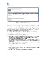
IP Interfaces: Configured IP interface with the use of either IPv4 or IPv6.  
The default interface is VLAN 1 with IP address of 10.100.7.247 for the Low 
Band radio and 10.100.7.248 for the High Band radio.  
The configurable fields in this section are: 


Delete: Select this option to delete an existing IP interface 


VLAN: The VLAN associated with the IP interface. Only ports in this VLAN 
will be able to access the IP interface. (This field is only available for input 
when creating a new interface.)


IPv4 DHCP Enable: Enable the DHCP client by checking this box. If this 
option is enabled, the system will configure the IPv4 address and mask of 
the interface using the DHCP protocol.  The DHCP client will announce the 
configured System Name as hostname to provide DNS lookup.  


IPv4 Fallback: The number of seconds for trying to obtain a DHCP lease. 
After this period expires, a configured IPv4 address will be use as IPv4 
interface address. A value of zero disables the fallback mechanism, such 
that DHCP will keep retrying until a valid address is obtained.  Range 
values are 0 to 4294967295 seconds 


IPv4 Address:  IPv4 address of the interface is dotted decimal notation. 
(If DHCP is enabled, this field configures the fallback address. The field 
may be left blank if IPv4 operation on the interface is not desired – or no 
DHCP fallback address is desired.)


IPv4 Mask: The IPv4 network mas, in number of bits (prefix length).  
Valid values are between 0 and 30 bits for an IPv4 address. (If DHCP is 
enabled, this field configures the fallback address network mask. The field 
may be left blank if IPv4 operation on the interface is not desired – or no 
DHCP fallback address is desired.)


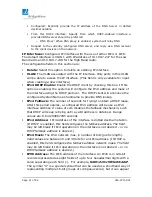
IPV6 Address: The IPv6 address of the interface. An IPv6 is in 128-bit 
records represented as eight fields of up to four hexadecimal digits with a 
colon separating each field (:).  For example, fe80::215:c5ff:fe03:4dc7
The symbol “:: is a special syntax that can be used as a shorthand way of 
representing multiple 16-bit groups of contiguous zeros; but it can appear 

Summary of Contents for FLEX4G-LITE

Page 1: ...6 FLEX4G LITE User Interface Manual 040 57105 01 ...

Page 2: ...ional and properly trained personnel and the customer assumes full responsibility when using the information herein The software provided and described in this guide is furnished under and is subject to a license and nondisclosure agreement Export Control All BridgeWave radio products are restricted commodities that fall under ECCN 5A002 of the Department of Commerce These products are ENC restric...

Page 3: ...dio 15 Connection to FLEX4G LITE 15 Radio Setup 18 Setting the Radio s IP Address 19 Detailed Status Page 23 Link Statistics Page 26 Configuration Page 27 Modem Firmware Upload Page 31 Installation Page 33 Diagnostics Page 35 Security Page 36 Factory Page 38 Logs Page 39 4 FLEX4G LITE Switch Functions 41 Switch Menu Options 41 5 UI MODEM Update Procedures via CLI 76 Tools and Methods 76 Update Usi...

Page 4: ...stem Log Entries 40 Figure 24 System Log Information Buttons 41 Figure 25 Switch Submenu Options 41 Figure 26 IP Multiple Management Interfaces 43 Figure 27 Save IP Configuration 43 Figure 28 VLAN Configuration 43 Figure 29 VLAN Port Access 44 Figure 30 NTP Configuration Page 45 Figure 31 Time Zone Configuration Page 46 Figure 32 System Log Configuration Page 47 Figure 34 User and Access Level 50 ...

Page 5: ... Software Upload 70 Figure 59 GUI Software Images 71 Figure 60 Save Running Configuration 72 Figure 61 Download Configuration Page 72 Figure 62 Upload Configuration 73 Figure 63 Activate Configuration s 74 Figure 64 Delete Configuration File 74 Figure 65 CLI Periodic Status Message 77 Figure 66 Software Upload 80 Figure 69 Controller Version 81 Figure 70 Software Image Selection 81 Figure 71 Modem...

Page 6: ...gners with a point to point broadband radio that delivers broadband wireless Ethernet IP based services Requiring no server room installation the all outdoor ready FLEX4G LITE installs quickly and delivers the lowest cost per gigabit wireless solution in the industry FLEX4G LITE is the ideal choice wherever rapid deployment of Carrier grade Ethernet service is required The FLEX4G LITE system consi...

Page 7: ...ts for general population exposure to radio frequency emissions however it is best to avoid prolonged unnecessary exposure to the waveguide opening while it is operating Please refer to Articles 810 and 830 of the National Electrical Code ANSI NFPA No 70 for installations in the U S A for information regarding proper grounding and applicable lightning protection for DC cables Outdoor equipment mus...

Page 8: ...es accidentally disconnected from the demarcation box There are no controls or adjustments other than power ON OFF that may be accessed by the user Risk of Personal Injury from Fiber Optics DANGER Invisible laser radiation Avoid direct eye exposure to the end of a fiber fiber cord or fiber pigtail The infrared light used in fiber optics systems is invisible but can cause serious injury to the eye ...

Page 9: ...rmation please contact BridgeWave at support BridgeWave com European Union This product has been designed to comply with CE markings in accordance with the requirements of European Directive 1995 5 EC This product has been designed to comply with the requirements of European Directives This equipment must be permanently earthed for protection and functional purposes To make a protective earth conn...

Page 10: ...ve may solely elect the Product as necessary so that the Product complies with the applicable Warranty or at BridgeWave s option refund to the Buyer the Buyer s purchase price paid for the Product Before returning any Products to BridgeWave Buyer must follow the steps set forth in the Trouble Shooting and Return Merchandise Procedure explained at www BridgeWave com Any Product returned to BridgeWa...

Page 11: ...ential information modify or create derivative works of or grant to any third party any rights in the Software or permit any third party to do any of these prohibited acts without BridgeWave s prior written consent Buyer agrees to protect the Software licensed hereunder in a manner consistent with the maintenance of BridgeWave s ownership and proprietary rights therein including displaying of any ...

Page 12: ...CHANNEL PARTNERS FOR THE PRODUCTS AND SOFTWARE Statute of Limitations Any action for breach of or to enforce any right under this Limited Hardware Warranty or Software License shall be commenced within one 1 year after the cause of action accrues or reasonably could have been discovered or it shall be deemed waived and barred Administrative Provisions This Limited Hardware Warranty and Software Li...
Page 13: ...Description The FLEX4G LITE millimeter wave radio is a point to point fixed wireless ultra high capacity broadband access product operating in the upper millimeter wave spectrum from 71 76 GHz and 81 86 GHz The FLEX4G LITE is capable of native Ethernet payloads from 83 3000Mbps full duplex The radio system is designed for rapid deployment In most locations the FLEX4G LITE will have a better than 9...

Page 14: ... 71 76 GHz RX 81 86 GHz 83 3000Mbps Slip Antenna ODU for use with external 30 60 90 cm antenna FLEX4G LITE H TX 81 86 GHz RX 71 76 GHz Table 1 FLEX4G LITE Model Additional configuration information is available in the FLEX4G LITE Product Description document available from BridgeWave or authorized representative ...

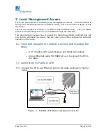
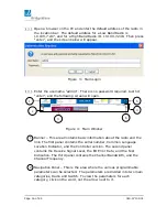
Page 15: ...through the Web GUI This document will explain how to access the radio through both methods but will only include command line details that are used in the initial configuration and basic operation of the radio Tools and equipment needed to access and manage the radio A PC or laptop with a web browser and telnet ssh enabled Use an Ethernet cable TIA 568B pin out to connect the PC to the radio Conn...

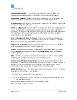
Page 16: ...dow 1 Banner This area Contains basic information about the radio and the link The first panel contains the serial number Common Language Location Indicator and the Controller version The second panel contains the Receive Signal Level the Bit Error Rate and the Test Indication The third panel contains the Channel Bandwidth and the Channel Frequency 2 Navigation Panel This is the area where the var...

Page 17: ...d clicking on a port will open another screen showing detailed port statistics 4 Log Out Button Clicking on this will log you out of the radio and open the login page 5 Help Button Clicking on this will open up a help window with help categories for the page from which it is opened 6 Refresh Button Clinking on this button will refresh the current page Selecting on the Auto refresh box causes the c...

Page 18: ...changes can be made it also displays the current status of the modem and the link Please be aware that any changes that are entered are only made to the radio to which you are currently connected and any changes made to Frequency Bandwidth Mute CW or Data Rate will take down an operating link until the same changes are made at the other end of the link Figure 5 Radio Setup Page ...

Page 19: ...to 22 dBm This feature only works with ATPC is selected Alignment Tx Power Enter a specific transmit power value This feature only works when Alignment mode is selected Mute Enable Mute to stop RF Transmission of the local radio The Mute Timeout value is configured under the Configuration page The default value is 10 mins CW Disables transmitter modulation and sends a constant carrier out the ante...

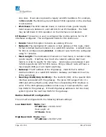
Page 20: ...p the new settings unless the startup config is saved This is done by navigating to the Save startup config page using the following link Switch Maintenance Configuration Save startup config This page is divided into three sections IP Configuration IP Interfaces and IP Routes Once all changes have been made click the Save button before proceeding to another page IP Configuration This section allow...

Page 21: ...e the configured System Name as hostname to provide DNS lookup IPv4 Fallback The number of seconds for trying to obtain a DHCP lease After this period expires a configured IPv4 address will be use as IPv4 interface address A value of zero disables the fallback mechanism such that DHCP will keep retrying until a valid address is obtained Range values are 0 to 4294967295 seconds IPv4 Address IPv4 ad...

Page 22: ...etwork or host mask in number of bits prefix length It defines how much of a network address that must match in order to qualify for this route Valid values are between 0 and 32 bits respectively 128 for IPv6 routes Only a default route will have a mask length of 0 as it will match anything Gateway The IP address of the IP gateway Valid format is dotted decimal notation or a valid IPv6 notation Ga...

Page 23: ...utside the subnet a default gateway needs to be configured The following example illustrates a unit configured to the 192 168 223 XXX subnet with outside subnet communication Figure 7 Sample Host IP Configuration Detailed Status Page Select from the navigation pane Radio Functions Detailed Status in opens the following screen ...

Page 24: ...Tx and Rx status Temperature The Temperature section panel displays the RF Transmitter baseband board and RF Receiver temperatures as well the SFP temperatures for both Port 2 and Port 3 These values are only available when an SFP module is inside the SFP cage IF Modem Status The IF Modem section displays information related to the state of the transmitter The transmitter can be set to Transmit Mu...

Page 25: ... the actual voltage in normal print Under the DC Input Voltage panel only the port or ports with actual power input will display true values Any of the ports with no input will display non real values Baseband Status The Baseband Status panel displays they type of SFP modules that are currently installed in the unit as well as basic information regarding their status ...

Page 26: ...d time when the Last Update was reported Statistics Description Severely Errored Seconds SES Number of seconds where the link had greater than 30 errored blocks for that second Errored Seconds ES Number of seconds where the link had one or more errored blocks for that second Unavailable Seconds UAS Number of seconds where the link was out of service Severely Error Periods SEP Number of periods tha...

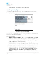
Page 27: ...L Alarm Threshold Red Default value 60 dBm If the signal falls below this value an alarm will be trigger as well as the indicator will turn red on the Modem Status under the Setup page The acceptable input range is from 80dBm to 20dBm NOTE The RSL indicator will change to Yellow when the RSL is between the RSL Alarm threshold Red and RSL Alarm threshold Green RSL Alarm Threshold Green Default valu...

Page 28: ...maximum value that can be set is 120 minutes User Logout Timer This control sets the time interval after which a CLI user will be logged out automatically if no activity is detected The time is set in minutes with a maximum value of 120 minutes This feature will not be set until the Save button is clicked Turn Off 1 minute Status to Console Port This checkbox when selected turns off the 1 minute p...

Page 29: ...unity string will be associated with the communities table If provides more flexibility to configure security name than version v1 and v2c community string In addition to community string a particular range of source addresses can be used to restrict source subnet Wire Community Indicates write string to permit access to SNMP agent The allowed string length is 0 to 255 characters and the allowed c...

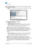
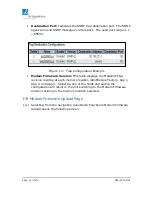
Page 30: ...of SNMP traps Mode Enable Disabled Delete Selecting this checkbox will delete the Trap Destination entry once the Save button is click Name Indicates the trap Destination Configuration s name Enable Indicates if that specific entry is either on or off Destination Address Indicates the SNMP trap destination address It displays an IP address in dotted decimal notation 1 1 1 1 It also allows a valid ...

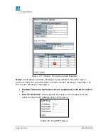
Page 31: ...re Version This table displays the Modem FPGA revision residing at each memory location identified as Factory App 1 App 2 and App 3 Selecting one of the fields and saving the configuration will result in the unit switching to the Modem Firmware Version residing in the memory location selected Modem Firmware Upload Page Selecting from the navigation pane Radio Functions Modem Firmware Upload opens ...

Page 32: ... Save button is click the unit will switch from the version residing in field App 1 to the version residing in field App 2 Modem Firmware Upload section is explained in detail in section 5 Pint TFTP Server This hyperlink will open a sub window that will allow to ping the IP address of the TFTP server Figure 16 Ping TFTP Server ...

Page 33: ... before any changes were made Only if the Save button has not been executed Installation Page Selecting from the navigation pane Radio Functions Installation opens the following screen Figure 167 Installation Pages This page is for information only and does not affect the operation of the radio These are two columns one column for information on the Local Radio and a second column for the same typ...

Page 34: ...ge 34 of 84 040 57105 01 Latitude of site where radio is located Longitude of site where radio is located Asset Tag of radio if one is assigned Customer Serial Number This field is used by the FLEX4G LITE ...

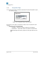
Page 35: ... 178 Diagnostic Page Fault Recovery The purpose of this page is to restart the radio as may be required for fault recovery Fault Recovery Select Module o Local ODU Select this module to restart the UI software o Local Modem Select this module to restart the modem FPGA Note Restarting either device module will interrupt traffic over the link ...

Page 36: ...Page 36 of 84 040 57105 01 Security Page Selection from the navigation pane Radio Functions Security Licensing will open the following screen Figure 189 Security Licensing Page ...

Page 37: ...UPG SYNC Software upgrade with Precision Timing Protocol PTP SyncE and 1588v2 FL4G LITE CPRI CPRI Firmware License for 2 458 Gbps Table 2 Available FLEX4G LITE Adaptive Rate Licenses Note To increase the capacity after purchasing a new license enter the Throughput key and or SyncE CPRI key supplied with the license in the first blank row of the corresponding table Throughput or SyncE CPRI License ...

Page 38: ... table allows the factory to entered Model Name Part Number Serial Number Min Tx Power and Max Tx power NOTE Do not make any change unless recommended by product support Licensing List This hyperlink provides quick access to the License List of Security Page Component Version This section provides read only information on the version of current Software and FPGA revision which includes Host Softwa...

Page 39: ...e navigation pane Radio Functions Logs will open the following screen Figure 191 Log Hyperlink Page The only option on this page is to select System Log Information hyperlink Once clicked the System Log Information page will display Figure 20 Log Page This page displays the event and performance history log Under System Log Information there are two pull down menus ...

Page 40: ... as follows ID The identification of the system log entry Level The level of the system log entry The types of level were defined above under the Level bullet Time The occurred time of the system log entry Message The detail message of the system log entry The Periodic Status Message format shown in Figure 20 can be decoded as 8 dBm Current Tx_Power level 64QAM Current tx_modulation Constellation ...

Page 41: ...tly displayed Updates the table entries starting from the last entry currently displayed Updates the table entries ending at the last available entry 4 FLEX4G LITE Switch Functions Switch Menu Options Selecting from the navigation pane Switch Figure 235 Switch Submenu Options The Switch menu options include Configuration The configuration of the radio s switch is implemented under these pages Moni...

Page 42: ...pages Information This page contains System Contact System Name and System Location IP This page contains the configuration required to access the unit s management interface via an IP address Each IP address is fixed to a specific VLAN ID This allows for the configuration of multiple IP address in different subnets in different VLANs The default Mode configuration is Host If the mode is change to...

Page 43: ...Figure 257 Save IP Configuration 2 Configured the port for VLAN access and allow the access to each VLAN Access this page Switch Configuration VLANs This page displays the default settings Figure 268 VLAN Configuration Save New configurat ion Entered new VLAN IDs to allow them access Ports 4 5 and 6 are configured to allow access to these new VLAN IDs ...

Page 44: ...N 10 10 100 7 x is connected to port 4 and pings are successfully sent to the management IP address 10 100 7 247 low band of the radio A PC VLAN tag 110 using the same IP address range of VLAN 110 is connected to port 5 and pings are successfully sent to the management IP address 110 10 10 1 of the radio This port also allows VLAN ID 1 and or untagged frames A PC VLAN tag 120 using the same IP add...

Page 45: ...ll reset the page back to previous settings Figure 28 NTP Configuration Page Time This page allows for the configuration of the Time Zone Time Zone List various Time Zones worldwide Select Time Zone from the drop down and click Save to set Acronym User can set the acronym of the time zone Range up to 16 characters Daylight Saving Time This is used to set the clock forward or backward according to ...

Page 46: ...ration Page Log System Log Configuration page Server Mode Enable Disable Default mode When the mode of operation is enabled the syslog will send messages to the syslog server configured under the Server Address field The syslog protocol is based on UDP communication and received on UDP port 514 Due to the nature of UDP no acknowledgments will be sent back during the communication between host and ...

Page 47: ...g server Options are Info Warning Error Save Button This buttons must be click to save the new settings before moving to another page Reset Button If configuration has been apply but has not been save clicking this button will revert the page back to previous settings Figure 30 System Log Configuration Page ...

Page 48: ...own Speed Current Provides the current link speed of the port Speed Configured Selects any available link speed for the given switch port Only speeds supported by the specific port are shown Possible speeds are o Disabled Turns port off o Auto Port auto negotiating speed with the link partner and selects the highest speed that is compatible with the link partner o 10Mbps HDX Forces the copper port...

Page 49: ...eed is selected on a port this section indicates the flow control capability that is advertised to the link partner When a fixed speed setting is selected that is what is used The Current Rx column indicates whether pause frames on the port are obeyed and the Current Tx column indicates whether pause frames on the port are transmitted The Rx and Tx settings are determined by the results of the las...

Page 50: ...The default configuration comes with admin and no password configured Privilege Level The privilege level of the user The allowed range is 1 to 15 If the privilege level is 15 the user is granted full control of the device User s privilege should be same or greater than the group privilege level to have access to that group By default most groups privilege level is configured to 5 which grants rea...

Page 51: ...he user The allowed range is 1 to 15 Note Privilege level setting is not available for Radio settings only Switch control settings Save Button This button must be click to save the new settings before moving to another page Reset Button If configuration has been applied but has not been saved clicking this button will reset the page back to previous settings Cancel Button This button will undo any...

Page 52: ...ration Page This page provides an overview of the privilege levels configured by default In most cases a privilege level group consists of a single module e g LACP RSTP or QoS however a few of them have access to more than one The following defines the Group Names and Privilege Levels Group Name System Contact Name Location TimeZone Daylight Savings Time Log Security Authentication System Access ...

Page 53: ...groups Configuration Read only Configuration execute read write Status statistics read only Status statistics read write e g for clearing of statistics Save Button This button must be click to save the new settings before moving to another page Reset Button If configuration has been applied but has not been saved clicking this button will reset the page back to previous settings Authentication Met...

Page 54: ...In this case the next method is tried Each method is tried from left to right and continues until a method either approves or rejects a user If a remote server is used for primary authentication it is recommended to configure secondary authentication as local This will enable the management client to login via the local user database if none of the configured authentication servers are available o...

Page 55: ...creen Figure 36 Authentication Method Configuration Page Hypertext Transfer Protocol over Secure Socket Layer HTTPS provides authentication and encrypted communication for sensitive communication HTTPS uses port 443 SSL uses a 40 bit key size for the RC4 stream encryption algorithm The Configuration page allows for the following settings Mode Enable Disable Default setting When Disabled the unit w...

Page 56: ...for the access management entry Start IP address Indicates the start IP address for the access management entry End IP address Indicates the end IP address for the access management entry HTTP HTTPS Indicates that the host can access the unit from HTTP HTTPS interface if the host IP address matches the IP address range provided in the entry SNMP Indicates that the host can access the switch from S...

Page 57: ...onfiguration SNMP Simple Network Management Protocol is part of the Transmission Control Protocol Internet Protocol SNMP Agent allows the radio to participate in a network management architecture Mode Enable Disable Version SNMPv1 SNMPv2c SNMPv3 Read Community Indicates read string to permit access to SNMP agent The allowed string length is 0 to 255 characters and the allowed content is the ASCII ...

Page 58: ... name than version v1 and v2c community string In addition to community string a particular range of source addresses can be used to restrict source subnet Engine ID Indicates the SNMPv3 engine ID The string must contain an even number in hexadecimal format with number of digits between 10 and 64 but all zeros and all F s are not allowed Change of the Engine ID will clear all original local users ...

Page 59: ...1 1 1 It also allows a valid hostname NOTE A valid hostname is a string drawn from the alphabet A Za z digits 0 9 dot dash Spaces are not allowed the first character must be in alpha character and the first and last characters must not be a dot or a dash Destination Port Indicates the SNMP trap destination port The SNMP agent will send SNMP messages via this port The valid port range is 1 65535 Fi...

Page 60: ...ess source address A particular range of source addresses can be used to restrict source subnet when combined with source mask Source Mask Indicates the SNMP access source address mask Add New Entry Button Adds a new community entry When click a new entry is display See image below Figure 43 SNMPv2 Community Configuration New Entry Save Button This button must be click to save the new settings bef...

Page 61: ...onfiguration of the Static Aggregation groups The system uses a Hash Code Algorithm to calculate per frame distribution between the group s member ports The system allows for the selection of specific frame s header information to run the Hash algorithm The following options are part of the frame s header and are used to generate the Hash Code Source MAC Address Destination MAC Address IP Address ...

Page 62: ...the aggregation By default no ports belong to any aggregation group Only full duplex ports can join an aggregation and ports must be in the same speed in each group Save Button This button must be click to save the new settings before moving to another page Reset Button If configuration has been applied but has not been saved clicking this button will reset the page back to previous settings ...

Page 63: ...t Column The switch port number LACP Enabled Controls whether LACP is enabled on the switch port LACP will form an aggregation when 2 or more ports are connected to the same partner Key The key value incurred by the port range 1 65535 o Auto The auto setting will set the key as appropriate by the physical link speed 10Mb 1 100Mb 2 1Gb 3 o Specific A user defined value can be entered Ports with the...

Page 64: ...ch ports will be in a backup role Lower number means greater priority Save Button This button must be click to save the new settings before moving to another page Reset Button If configuration has been applied but has not been saved clicking this button will reset the page back to previous settings Example of LACP Configuration Creates a 2Gbps bond Ports 4 and 5 are bonded via LACP group using spe...

Page 65: ...00 1000Mbps ports 2 Ports 2 3 are SFP cages These ports can be used with Fiber MM or SM Cupper and or CPRI SFP modules Wireless Ports 7 10 1 Each port is 1000Mbps 1Gbps ports capable 2 Each port receives a fraction of the total available wireless bandwidth Examples 1 2Gbps wireless link Port 7 8 9 10 are on Each port gets 500Mbps 2000Mbps 4 ports 2 3Gbps wireless link Port 7 8 are on Each port onl...

Page 66: ...r the mouse cursor over the top of each port and the current state will display Click on a port Clicking on a port will open the Detailed Port Statistics page for that port Figure for example counters Figure 48 Example of Detailed Port Statistics Utility Buttons Figure 49 Utility Buttons ...

Page 67: ...s divided into 6 columns and is describe as follow Port The logical port for the settings contained in the same row Packets The number of received and transmitted packets per port Bytes The number of received and transmitted bytes per port Errors The number of frames received in error and the number of incomplete transmission per port Drops The number of frames discarded due to ingress or egress c...

Page 68: ...m frame length for this port Rx Fragments The number of short frames received with invalid CRC Rx Jabber The number of long frames received with invalid CRC Rx Filtered The number of received frames filtered by the forwarding process Tx Drops The number of frames dropped due to output buffer congestion Tx Late Exc Coll The number of frames dropped due to excessive or late collisions Port Selection...

Page 69: ... following screen Figure 52 Factory Defaults This page allows for reverting of the configuration on the unit to factory settings Only the IP address configuration is retained The default configuration is available immediately which means that no restart is necessary Yes Button Click to reset the configuration to Factory Defaults No Button Click to return to the Port State page without resetting th...

Page 70: ...the switch and the interfacing with the unit NOTE Radio FPGA code is loaded via the CLI interface Choose File Button Use this button to locate the new software to be uploaded into the system Upload Button Click to upload the file once the file has been selected NOTE After the software image is uploaded a page announces that the firmware update is initiated After about a minute the firmware is upda...

Page 71: ... memory location and it is use to revert the device to this version if the current image fails The table provides the following information regarding the images Image The flash index name of the firmware image The name of primary preferred image is managed the alternate image is name managed bk Version The version of the firmware image A condensed image name version is also available under the Fac...

Page 72: ...hanges will need to be store in nonvolatile memory location If this is not performed all changes will be lost once the unit reboots This page contains one Save Configuration button Clicking on this button will save the configuration into the Running Configuration memory location and a message of a successful save will display Download Configuration Selecting from the navigation pane Switch Mainten...

Page 73: ...he switch configuration This is done in two ways Replace Mode The current configuration is fully replaced with the configuration file uploaded Merge mode The uploaded file is merged into running config NOTE If the file system is full i e contains all three system files plus two other files it is not possible to create new files One of the existing files must be overwritten or deleted first Choose ...

Page 74: ...g Custom config Select the file to active and click the Activate Configuration button This will initiate the process of completely replacing the existing configuration with that of the selected file Delete Selecting from the navigation pane Switch Maintenance Software Delete opens the following screen Figure 59 Delete Configuration File This page allows the deletion of any files stored in flash in...

Page 75: ...Page 75 of 84 040 57105 01 Select the file to delete and click the Delete Configuration File ...

Page 76: ...FTP server is required to host the new UI package Follow this step to perform the update 1 Copy the FLEX4G LITE UI upgrade file to a known location on the host PC The upgrade file extension ends with gz 2 Start a TFTP server NBTFTP exe on the host PC 3 Set the search directory of the TFTP server to the directory where the upgrade software is located 4 Open a Command window on the host PC 5 Telnet ...

Page 77: ...race module level eband_fpga default none 9 The syntax for uploading the UI image uses the follow CLI command debug firmware managed bk ip_addr of TFTP server file name LITExxx gz For example debug firmware load managed bk 10 100 7 3 LITE0004 gz The command tells the radio software to load into the backup image memory location the UI image available from the TFTP server located at 10 100 7 3 with ...

Page 78: ... CPU modem firmware package 1 Start the TFTP server on a PC that the FLEX4G LITE radio has access 2 Copy new FPGA CPU modem code to the TFTP server directory 3 Start up a telnet session to the target FLEX4G LITE radio telnet ip_addr 4 Enter user name admin and password enter or return at the prompts 5 Enter Determine which of the three available memory locations will be used to store the new code ...

Page 79: ... from ip_addr file name passed length modem file size CRC correct file size in hex Sending image Commit the upload to flash memory type the following command sequence upgrade cpu burn x Where x flash memory slot x 1 2 or 3 Do not attempt to load into the operational memory slot as determined in step 5 above If this slot is selected upload will not commit to flash memory The commit to flash memory ...

Page 80: ...ther update will interrupt the link and or bring the link down during the process It is recommended to have a maintenance window in place before beginning the process Updating the UI click on the Switch Maintenance Software Upload to access to the software upload page Figure 66 Software Upload 1 Click on Choose File and navigate to the folder were the new UI software was previously download it to ...

Page 81: ...e Select page after the upload the new image will be display under the Active Image section Click on Switch Maintenance Software Image Select to access the Software Image Selection Figure 68 Software Image Selection Note The previous Active image will become the Alternate Image ...

Page 82: ...r the File Name Example qam bin 2 Enter File Size and File Checksum These values are found in the qam checksum txt file that is included with the new software code package 3 Select the Location This will be one of the other two locations that is not currently Active or selected Figure 70 Modem Firmware Version Location 4 Enter the TFTP server IP address On this example the TFTP server is running u...

Page 83: ...mware revision As displayed on Figure 65 above Location App 3 was selected Therefore App 3 will need to be check to active the new code Figure 72 Modem Firmware Version Selection 7 Click Save to active the new code 8 Verify the new modem firmware select Radio Functions Factory to access the page The new version will be displayed under the Modem Firmware Version field Figure 73 Modem Firmware Versi...

Page 84: ...y further assistance contact BridgeWave Support via e mail at support bridgewave com End of Manual Digitally signed by K Spitz DN cn K Spitz o ou REMEC Broadband Wireless email karla spitz remecbroadband com c US Date 2016 11 11 10 38 09 08 00 ...

Reviews: