25
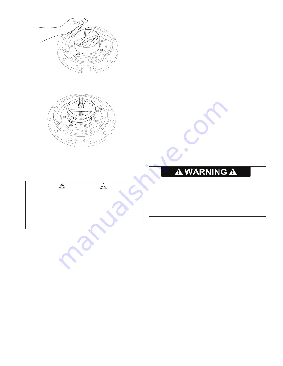
7. Install the piston stop (Item 92) and the brake spring
(Item 91).
8. Set the spring stop (Item 93) on the spring and install
the spring compressor tool, or move the assembly to
a press. Be sure the step on the compressor tool is
squarely seated on the spring stop.
9. Slowly compress the spring until the spring stop is
slightly below the retaining ring groove in the motor sup-
port. Install the retaining ring (Item 94).
NOTE:
The holes in the ends of the retaining ring are
slightly tapered. The smaller end of the hole
MUST
be installed away from the spring stop, or toward the
motor, to prevent the ring from slipping off the pliers
when installed or removed. Be sure the retaining ring is
completely seated in its groove, and slowly release the
spring compressor until the force of the spring is held by
the retaining ring. Remove the spring compressor tool.
Brake Cylinder Pressure Test
1. Connect a hydraulic hand pump with an accurate gauge
and shut-off valve to the brake release port of the motor
support. Apply 500 PSI (3,450 kPa) to the brake. Close
the shut-off valve and let stand for five minutes. If there
is any loss of pressure, the brake cylinder should be
disassembled for inspection of the sealing surfaces and
O-rings.
WHILE PRESSURE IS APPLIED AND THE BRAKE IS
RELEASED, install the sprag clutch assembly. Rotate the
clutch back and forth to align the splines in all brake discs.
When the sprag clutch has engaged all the discs, release
the pressure on the brake cylinder and remove the sprag
clutch.
Sprag Clutch Assembly
Before disassembling the sprag clutch, make note of the
freewheeling direction of the inner brake race (Item 102).
Hold the outer race (Item 96) and try to turn the inner race
in both directions. It should turn free of the outer race
in one direction only. If the inner race will not turn freely
in either direction, or turns freely in both directions, the
sprag clutch assembly has been damaged and must be
replaced.
1. Remove the retaining ring (Item 104). All other internal
parts can now be removed, including the sprag assem-
bly (Item 99) and the roller bearing (Item 97).
2. Thoroughly clean all parts in solvent and inspect for
signs of wear and/or damage. Inspect the sprag clutch
and roller bearing closely for abnormal wear, cracks,
pitting or corrosion. Check small clips for breakage or
bright spots; the signs of excessive wear.
3. Apply a light coat of gear box lubricant to all components
as they are assembled. Install the roller bearing (Item
97) into the outer race (Item 96). Install spacer (Item
98) on top of roller bearing. Install the sprag clutch as-
sembly (Item 99).
NOTE:
The sprag assembly con-
sists of three parts; two U-shaped bronze spacers and
a cam assembly. The bronze spacers are installed with
their open end toward the cam assembly, one spacer
on each side. Rotate the cam assembly while gently
pressing it into the outer race.
Before installing the inner race (Item 102), be sure the
internal retaining ring (Item 101) is installed and fully seat-
ed. Slide the inner race through the sprag clutch (the race
will have to be rotated in the freewheeling direction to start
it into the clutch). Be sure the inner race turns freely in
the same direction determined before the unit was disas-
sembled. If it turns freely in the opposite direction, the
sprag clutch has been installed backwards and must be
reversed. Install spacers (Items 100 and 103), and retain-
ing ring (Item 104).
The brake spring must be compressed approximately
4 inches (10 cm) and has a compressed force of ap-
proximately 1,500 lb (680 kg). Extreme care should be
observed while completing this step to avoid sudden
release of the spring.
DO NOT
stand directly in front of
the spring while it is being compressed.
CAUTION
The polished surfaces of the inner and outer races must
be perfectly smooth to ensure positive engagement of
the clutch. The slightest defect may reduce sprag clutch
effectiveness, which could result in property damage,
personal injury, or death. The entire sprag clutch as-
sembly must be replaced if any component is defective.
Summary of Contents for CH330
Page 2: ...2...


