


18
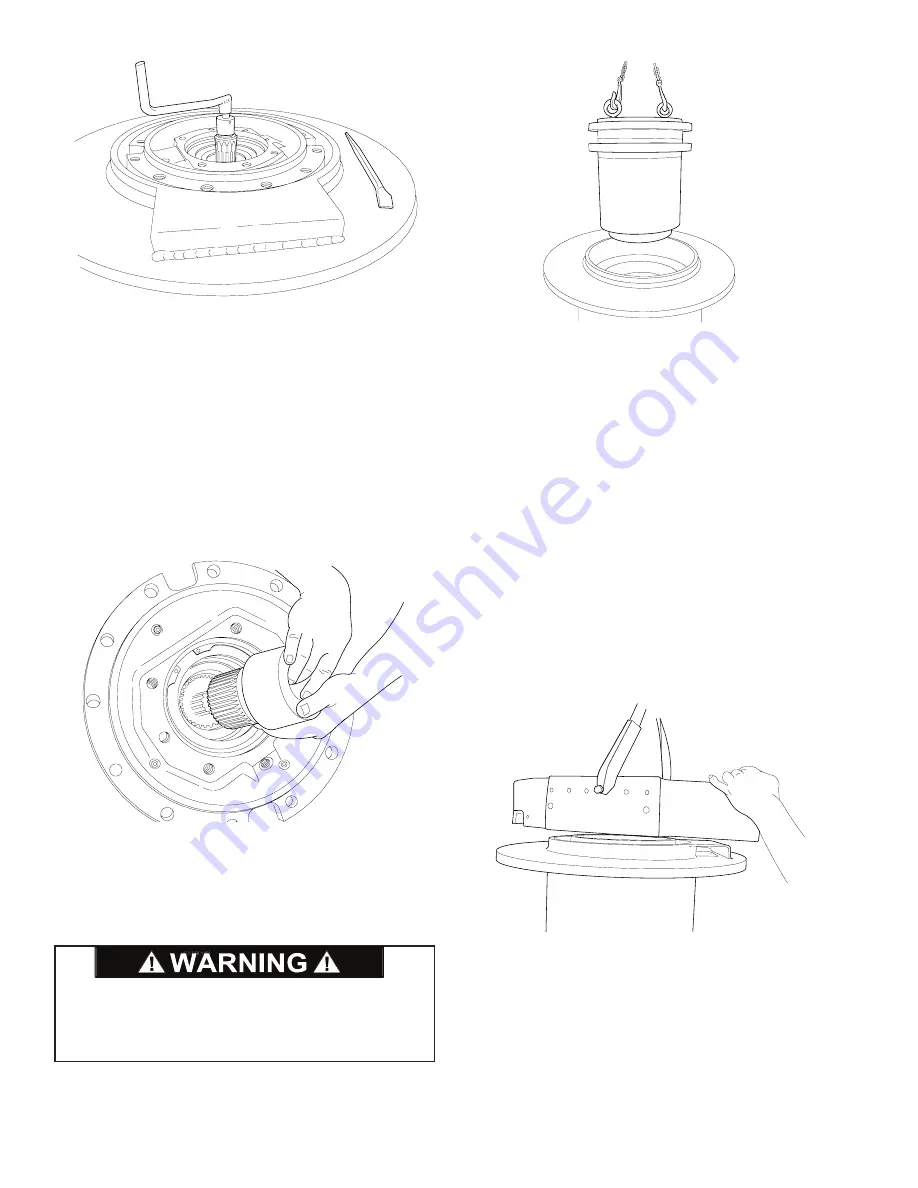
6. There are two large notches in the end of the drive
gearbox. These must be rotated to gain access to the
capscrews and lockwashers (Items 4 and 5) that secure
the gearbox to the winch drum. This is done by rotating
the motor coupling while keeping the drum from turning.
Continue this procedure and remove all capscrews and
lockwashers (Items 4 and 5).
NOTE:
To obtain relative movement between the two
sections of the gearbox, the input shaft must be rotated
in the same direction as the motor turns to haul-in ca-
ble. Rotating the shaft in the opposite direction results
in the entire gearbox and drum turning as a single unit.
7. The brake clutch assembly and motor coupling should
now be removed from the gearbox.
NOTE:
The sun gear will remain in the gearbox and
cannot be removed from this end.
8. Lift the winch drive gearbox out of the drum using two
7/8 NC eyebolts spaced 180 degrees apart as lifting
lugs. Refer to Winch Drive/Gearbox Service section for
further disassembly of winch drive.
DRUM SUPPORT
END BRACKET SERVICE
If the winch disassembly procedure has been followed to
this point, remove the C-clamps installed in step 4. If only
this end of the winch is being serviced, support the winch
on the motor end bracket and remove the 12 capscrews
and lockwashers securing the end of both tie plates (Item
1), to the drum support end bracket (Item 2). Loosen
the 12 capscrews on the other end of both tie plates just
enough to allow the tie plates to be pried free of the dowel
pins in the drum support end bracket.
1. Lift the support end bracket from the drum.
NOTE:
If the winch disassembly procedure was fol-
lowed and the drum is on top of the end bracket, lift the
drum from the support end bracket.
DO NOT attempt to remove the large retaining ring at
this time. It is holding the static brake spring in com-
pression. Removing this retaining ring at this time could
result in property damage, personal injury, or death.
Summary of Contents for CH330
Page 2: ...2...