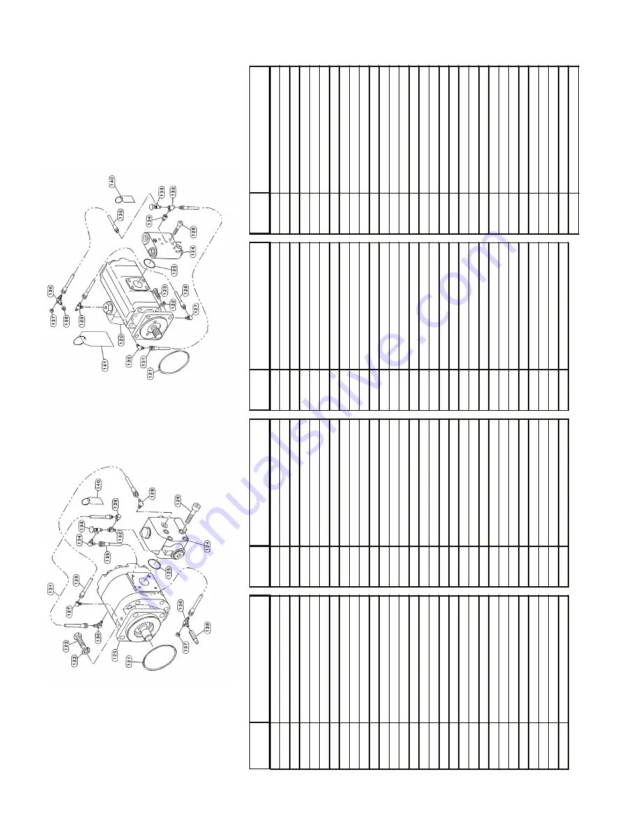
background image

20

Two-speed

Motor

Single-speed

Motor

ITEM

ITEM

ITEM

ITE

M

NUMBE

DESCRIPTION

NUMBE

DESCRIPTION

NUMBE

DESCRIPTIO

NN

UMBE

DESCRIPTIO

N

1T

ie Plat

e3

1D

ow

el Pi

n6

7S

econd Stage Planet Carrier

97

Roller Bearin

g

2S

upport End Plat

e3

2P

ipe Plug

68

Planet Pi

n9

8S

pace

r

3O

-Ring Flush Plug

33

Capscrew

69

Th

rust 

Wa

sher

99

Sprag Clutch Assembly

4L

ockw

ashe

r4

0T

hrust 

Wa

sher

70

Second Stage Planet Gear

10

0S

pace

r

5C

apscrew

41

Th

rust 

Wa

sher

71

Loose Roller

s1

01

Internal Retaining Ring

6O

uter Bearing Hu

b4

2

Primary Ring Gear/End Cove

r7

2O

utput Planet Carrie

r1

02

Sprag Clutch Inner Race

7I

nternal Retaining Ring

43

Capscrew

73

Planet Pi

n1

03

Spacer

8R

oller Bearin

g4

4

Lockw

ashe

r7

4B

earing Cone

10

4I

nternal Retaining Ring

9G

rease Fittin

g4

5R

ing Gear

75

Bearing Cu

p1

05

Cable 

We

dge (01 & 02 Drum

)

10

Inner Bearing Hu

b4

6D

rain Tube

76

Output Planet Gear

10

6C

able 

We

dge (03 & 04 Drum

)

11

Ex

ternal Retaining Ring

47

Plug

77

Bearing Spacer

12

0H

ydraulic

 Mo

to

r

12

Seal

48

Split Ring

78

Internal Retaining Ring

12

1O

-Rin

g

13

Seal Carrier

49

Bearing Cone

79

Rollpin

12

2L

ockw

ashe

r

14

O-Ring

50

Bearing Cu

p8

0P

lu

g1

23

Capscrew

15

Lockw

ashe

r5

1B

earing Cu

p8

1I

nternal Retaining Ring

12

4B

rake Valv

e

16

Capscrew

52

Bearing Cone

82

Brake Spacer/Support Plat

e1

25

O-Ring

17

Capscrew

53

Me

tal Face Seal

83

Steel Brake Disk

12

6C

apscre

w

18

Lockw

ashe

r5

4V

ent Plug

84

Friction Brake Disk

12

7R

educer Elbo

w

19

Sight Gauge

55

Primary Sun Gear

85

Mo

tor Support/Brake Cylinder

12

8H

ydraulic

 Hose

20

Capscrew

56

Ex

ternal Retaining Ring

86

Back-Up Ring

12

9E

lbow

 Fittin

g

21

Cover Plat

e5

7T

hrust 

Wa

sher

87

O-Ring

13

0E

lbow

 Fittin

g

22

O-Ring

58

Second Stage Sun Gear

88

O-Ring

13

1H

ydraulic

 Hose

23

Cable Drum

59

Primary Planet Carrie

r8

9B

ack-Up Ring

13

2T

ee Fitting

24

O-Ring

60

Planet Pi

n9

0

Brake Piston

13

3N

eedle Valv

e

25

Mo

tor End Plat

e6

1T

hrust 

Wa

sher

91

Brake Spring

13

4E

lbow

 Fittin

g

26

O-Ring

62

Primary Planet Gear

92

Brake Piston Stop

13

5H

ydraulic

 Hose

27

Mo

tor Adapte

r6

3

Loose Roller

s9

3S

pring Stop

13

6M

ale Branch 

Te

e Fitting

28

Mo

tor Couplin

g6

4R

ollpin

94

Internal Retaining Ring

13

7C

ap Nu

t

29

Capscrew

65

Th

rust 

Wa

sher

95

Bushin

g1

38

Nipple

30

Lockw

ashe

r6

6O

utput Sun Gear

96

Sprag Clutch Outer Race

13

9E

lbow

 Fittin

g

14

0W

arning 

Ta

g

Summary of Contents for CH330

Page 1: ...manufactured For serial number location see page 4 Visit our Web site at www paccarwinch com for the most comprehensive collection of winch hoist and drive information on the Internet Most publication...

Page 2: ...2...

Page 3: ...Hydraulic Circuits 10 Preventive Maintenance 11 Weights Oil Capacities and Special Tools 13 Troubleshooting 14 Service Precautions 17 Winch Disassembly 17 Drum Support End Bracket Service 18 Exploded...

Page 4: ...been removed for illustrative purposes Drawings in this manual represent a typical unit sold through our distribution channels Some hoists particularly those sold directly to original equipment manufa...

Page 5: ...ments listed in the Preventive Maintenance section of this manual 9 An equipment warm up procedure is recommended for all start ups and is essential at ambient tempera tures below 40 F 4 C Refer to Wa...

Page 6: ...nt and modulates the spool valve opening which controls the lowering speed See Figures 1 2 and 3 The static brake system has three operating components 1 Spring applied hydraulically released multiple...

Page 7: ...d is absorbed by the hydraulic oil where it can be readily dissipated When the control valve is shifted to neutral pilot pressure drops closing the brake valve spool stopping the motor and the load Th...

Page 8: ...give good results un der normal temperature conditions The use of an oil hav ing a high viscosity index will minimize cold start trouble and reduce the length of warm up periods A high vis cosity inde...

Page 9: ...ll seat against the flat end Install the washer and locknut onto the threaded rod and tighten securely to 45 ft lbs This is the torque value of the 1 2 13 stainless steel rod Apply a light load of 1 0...

Page 10: ...need for emergency servicing and promote safe 2 Oil Change 3 The gear oil should be changed after the first one hundred 100 hours of operation then every 1 000 operating hours or six 6 months whicheve...

Page 11: ...hever occurs first The gear oil must be changed to remove wear particles that impede the reliable and safe operation of the brake clutch and erode bearings gears and seals Failure to change gear oil a...

Page 12: ...life For simplicity we have listed one readily available product in each temperature range which has been tested and found to meet our specifications This is not to say that other lubricant brands wou...

Page 13: ...ive 12 point 5 8 inch Proto P N J07510T Snap On P N IMD202A 3 4 inch Proto P N J07512T Snap On P N IMD242A APPROXIMATE APPROXIMATE DRUM WEIGHT LBS KG OIL CAPACITY QTS L 01 2700 1225 40 38 02 3370 1530...

Page 14: ...placement of the seals Refer to Motor Support Brake Cylinder Service Disassemble brake to inspect brake discs B Oil leaks from vent plug 1 Same as A1 2 Motor seal may be defective as a result of high...

Page 15: ...adjustment or re pair 3 Be certain hydraulic system tempera ture is not more than 180 F 82 C Excessive hydraulic oil temperatures increase motor internal leakage and re duce motor performance 4 Winch...

Page 16: ...aining as required G The wire rope does not spool smoothly on the drum 1 The winch may be mounted too close to the main sheave causing the fleet angle to be more than 1 1 2 degrees 2 The winch may not...

Page 17: ...gears and bearings Item numbers shown in service procedures are referenced to the exploded view drawing in this manual WINCH DISASSEMBLY 1 Stand the winch of the end opposite the motor Re move the hy...

Page 18: ...eyebolts spaced 180 degrees apart as lifting lugs Refer to Winch Drive Gearbox Service section for further disassembly of winch drive DRUM SUPPORT END BRACKET SERVICE If the winch disassembly procedur...

Page 19: ...6 9 6 4 7 3 7 4 7 5 7 6 7 9 7 7 6 1 6 3 6 2 6 1 5 6 6 7 6 5 6 6 7 2 5 8 5 7 6 4 6 0 5 9 5 6 5 5 4 0 4 1 4 2 4 4 4 3 8 1 8 2 4 5 4 5 8 0 5 1 5 2 5 3 4 7 4 6 5 0 4 9 4 8 7 8 7 5 7 4 8 3 8 4 8 5 3 2 5 4...

Page 20: ...al Carrier 49 Bearing Cone 79 Rollpin 122 Lockwasher 14 O Ring 50 Bearing Cup 80 Plug 123 Capscrew 15 Lockwasher 51 Bearing Cup 81 Internal Retaining Ring 124 Brake Valve 16 Capscrew 52 Bearing Cone 8...

Page 21: ...ng carrier end cap Install a new retaining ring into the groove in the end cap Liberally pack the bearing and end cap with grease The end bracket can now be placed on the drum or the drum placed on th...

Page 22: ...Install three 7 8 9x6 inch long capscrews equally spaced around the motor support Item 85 until they contact the ring gear Item 45 Alternately tighten each capscrew 1 2 to 1 turn at a time to lift the...

Page 23: ...he brake piston Place each friction disc on a flat surface and check for distortion with a straight edge Friction material should appear even across the entire surface and the groove pattern should be...

Page 24: ...n disc It is advisable to lightly lubricate the brake discs with oil that will be used in the winch prior to assembly 3 Install the spacer plate Item 82 on top of the last fric tion disc 4 Install the...

Page 25: ...ged and must be replaced 1 Remove the retaining ring Item 104 All other internal parts can now be removed including the sprag assem bly Item 99 and the roller bearing Item 97 2 Thoroughly clean all pa...

Page 26: ...and inspect for damage and wear The bearings should be examined for any signs of spalling corrosion discoloration material displacement or abnormal wear The bearing cages should be inspected for wear...

Page 27: ...d wear The bearing rollers should be examined for any signs of spalling corrosion discoloration material dis placement or abnormal wear If any of these conditions are found the rollers should be repla...

Page 28: ...or end down Apply a light coat of oil to the mating surfaces of the metal seal and set the ring gear down onto the motor support Mat ing surfaces of the seal should be in contact with each other and t...

Page 29: ...m before proceeding 7 Install thrust washer Item 57 onto the primary planet assembly with second stage sun gear A light coat of oil soluble grease should be used to hold it in place during assembly In...

Page 30: ...ligning the holes in the drum with those in the bottom flange of the drive 13 There are two large notches in the end of the drive gearbox These must be rotated to install the cap screws and lockwasher...

Page 31: ...dapter into the winch drive using four capscrews and lockwashers Items 33 and 4 18 Install the motor coupling into the inner race of the sprag clutch 19 Install a new O ring Item 121 onto the pilot of...

Page 32: ...e additional thickness of the spring seat and a groove ma chined into the hex end cap serves as a visual indicator that the valve contains the new spring seat The spring seat improvement may be added...

Page 33: ...h Valve 1 1 2 inch Valve 2 Remove the fitting motor drain check ball and spring 1 1 4 inch Valve 1 1 2 inch Valve 3 Remove the spool spring retainer and spool spring Remove the spool plug and carefull...

Page 34: ...ch backup ring is on the correct side of its O ring Take care not to cut the O rings during assembly Let the spool and piston set for ten minutes before installing them in their respective bores This...

Page 35: ...s as the applied torque may vary by 10 40 depending upon product used To convert lb ft to kg m multiply lb ft value by 0 1383 Dry Lubed Dry Lubed Dry Lubed Dry Lubed Torque LB FT Grade 5 Grade 8 1 4 2...

Page 36: ...g 60o F pounds sq in PSI X 6 895 kilopascals kPa kilopascals kPa X 0 145 pounds sq in PSI pounds sq in PSI X 0 0703 kilograms sq cm kg cm2 kilograms sq cm kg cm2 X 14 22 pounds sq in PSI pounds sq in...

Reviews: