background image


Assembly of the WS200 work station  57/92 


DCA_DE_000151/10-2013, WS200, 

Bosch Rexroth AG


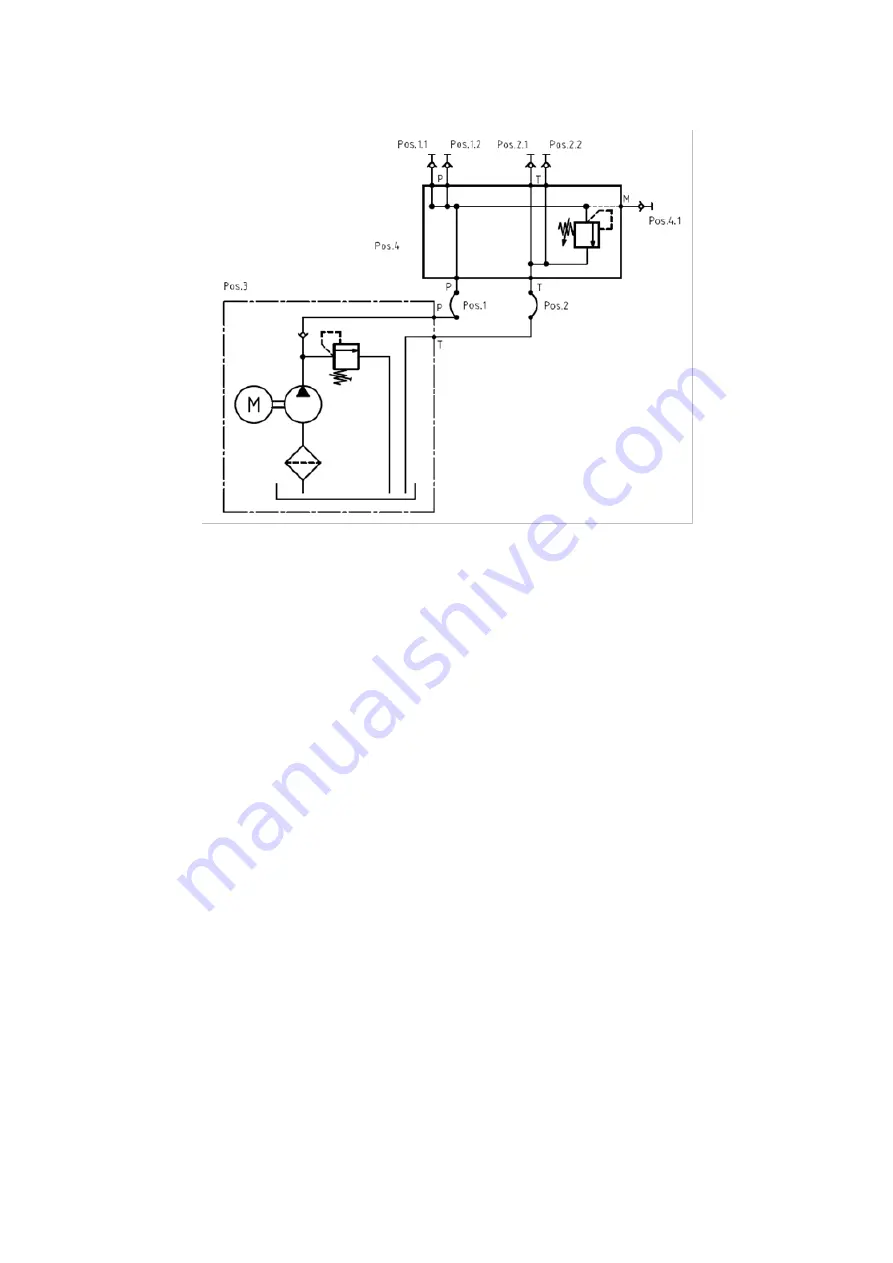
1  Pressure line  

1.1 / 1.2  Coupling connector - port P 

2  Line to the tank  

2.1 / 2.2  Coupling connector - port T 

3  ANTRIEBSAGGREGAT TS-WS200 220V/50HZ 1X 

4  P/T distributor 

4.1  Minimess coupling - connection of the hydraulic measuring line 

Fig. 41:


Hydraulic circuit schematic WS200  


Summary of Contents for Rexroth WS200

Page 1: ...WS200 work station Operating instructions DCA DE 000151 10 2013 Replaces English ...

Page 2: ...verification It must be remembered that our products are subject to a natural process of wear and aging This document as well as the data specifications and other information set forth in it are the exclusive property of Bosch Rexroth AG It may not be reproduced or given to third parties without its consent The cover page shows an example configuration The product supplied may therefore differ fro...

Page 3: ...lve 38 7 4 3 Tray 39 1 1 Validity of the documentation 5 1 2 Necessary and amending documentation 5 1 3 Representation of information 6 2 1 General information on this chapter 7 2 2 Intended use 8 2 3 Improper use 8 2 4 Qualification of personnel 9 2 5 General safety instructions 10 2 6 Product and technology dependent safety instructions 11 2 7 Personal protective equipment 13 2 8 Obligations of ...

Page 4: ... 1 Setting the WS200 work station up 58 8 2 Checking the hydraulic supply 59 8 3 Filling the oil tank 59 8 4 Electric installation 61 8 5 Initial commissioning of the compact hydraulic power unit 62 9 1 Switch on of the work station in hydraulic form 63 9 2 Switch off 64 9 3 Resetting the EMERGENCY OFF 64 9 4 Mounting variant for installation into the grid 65 9 5 Mounting technique for attachment ...

Page 5: ...king with the product 1 2 Necessary and amending documentation The product must not be commissioned until you have been provided with the documentation marked with the book symbol see table 1 and you have understood and observed it Table 1 Necessary and amending documentation Title Document number Document type Hydraulic fluids on mineral oil basis and related hydrocarbons RE 90220 Data sheet Hydr...

Page 6: ...er Specifies the type and source of danger Consequences Describes the consequences of non compliance Precautions Specifies how the danger can be prevented The following table shows an overview of the individual warning levels starting with Notice up to Danger It describes the risk in case of non compliance with the safety instruction Table 2 Risk classes according to ANSI Z535 6 2006 Warning sign ...

Page 7: ...draulic power unit MD Tightening torque of the connection elements in Nm 2 Safety instructions 2 1 General information on this chapter The product has been manufactured according to the generally accepted codes of practice However there is still the risk of personal injury and damage to property if you do not observe this chapter and the safety instructions in this documentation Before the commiss...

Page 8: ...mation on damage to property and damage to the product 2 3 Improper use Any use deviating from the intended use is improper and thus inadmissible The installation or use of inappropriate products in safety relevant applications could result in unintended operating conditions when being used which in turn could cause personal injuries and or damage to property Therefore please only use a product fo...

Page 9: ...rized specialist personnel or persons being sufficiently qualified and entitled Persons authorized to perform work at the work station have to be able to follow the information provided in this documentation and to perform in addition and independently any information possibly missing due to their personal professional qualification 2 4 3 Troubleshooting maintenance and repair Maintenance and repa...

Page 10: ...n Observe the safety regulations and provisions of the country where the product is implemented used Exclusively use Bosch Rexroth products in good technical order and condition Observe all notices on the product Persons who assemble operate disassemble or maintain Bosch Rexroth products must not consume any alcohol drugs or medication that may affect their ability to react Only use accessories an...

Page 11: ...raulic power unit to a value of more than 70 bar Danger due to faulty assembly and installation Risk of serious injury in the subsequent operation Have maintenance works performed by specialist personnel only Lay connection cables so that they do not constitute a risk of tripping Leaking oil mist Risk of fire risk due to allergic reactions environmental pollution Only carry out repair and maintena...

Page 12: ...r to bind the leaked hydraulic fluid Dispose of any supplies and auxiliary materials spilled and used as prescribed pursuant to the country specific legal provisions Hot surfaces during and after operation Risk of injury Risk of burning Only touch the surfaces of the hydraulic power unit and the hydraulic training components with protective gloves Especially actuation solenoids for electrically op...

Page 13: ...s respect they pay particular attention to that the ground is sufficiently load bearing and even and horizontal ensure that the accident prevention regulations the safety regulations of the professional unions as well as further internal and local requirements are observed They instruct their employees and or those of third party companies on possible dangers at the place of installation The machi...

Page 14: ... the motor protection relay function the circuit arrangement in the control box has another function Protection against automatic start up of the hydraulic power unit after an interruption in the supply voltage This may e g be the case if the mains plug is pulled out of the mains socket while the hydraulic power unit is switched on If this is the case the hydraulic power unit can be switched on ag...

Page 15: ...ng on the equipment type 2 10 Operator workplaces The following space is to be provided for the operation of the work station by the operator Fig 1 Space required in cm WS200 Depending on the use of the WS200 work station the following training places are provided for Table 5 Training places at one side of the work station Work step Recommended number of persons Set up 2 Operation 2 Mechanical saf...

Page 16: ... getting into the hydraulic lines and causing wear or malfunctions Before commissioning ensure that all hydraulic and mechanical connections have been made During filling filter the hydraulic fluids using a suitable filter system in order to minimize the solid particle contamination in the system Pressurized and live system Damage to property Do not disconnect lines connections or components as lo...

Page 17: ...m or unmounted for self assembly For a more detailed description of the available mounted variants of the WS200 work station please refer to chap 5 10 The work station will in each case be packed in a wooden box Details regarding the scope of delivery according to the order confirmation Fig 2 Mounted variant of the WS200 work station Fig 3 Unmounted variant of the WS200 work station ...

Page 18: ...tension possibilities with regard to the space required by the training area A connection kit allows for the coupling of two work stations in this way the space of the training area is doubled Due to the small dimensions it is perfectly suited as entry level package for the world of hydraulics and pneumatics All this turns the WS200 work station into a complete customer specific training and furth...

Page 19: ...rier is equipped with four stable lockable and steerable transport rollers 2 and an oil pan 3 The oil pan is used to collect drip losses at the hydraulic power unit and drip losses of hydraulic hose lines at the hose holder In a configuration with pneumatic set up you an also place a compressor for the compressed air supply in this oil pan 1 Device carrier 2 Transport rollers 2 1 Locking device of...

Page 20: ...ce with hydraulic fluid 1 Oil tank 3 Asynchronous one phase motor 1 1 Oil level display 4 Control box with connection line 1 2 Measuring glass connection 5 Cross member 1 3 Filler neck 6 External gear pump 2 Central connection block 7 Vibration damper 2 1 Pressure relief valve 2 2 Pressure line port P 2 3 Tank line port T Fig 6 Individual compact hydraulic power unit ...

Page 21: ...matic Fig 7 Circuit schematic of an individual compact hydraulic power unit 5 4 3 Control box 1 Control box 4 EMERGENCY OFF pushbutton 2 Off pushbutton 5 Cable holder for power cable 3 On pushbutton 6 Power cable with mains plug 7 Micro fuse for control line Fig 8 Control box and electrical circuit schematic ...

Page 22: ...s one phase motor is used to drive the external gear pump Mechanically the motor is connected to the pump via an elastic coupling This prevents vibrations and thus reduces the noise level Cooling of the motor during operation is realized by a directly flanged fan The voltage supply of the hydraulic power unit is effected via the control box The control box is equipped with an On pushbutton green f...

Page 23: ...endent i e there is neither a hydraulic nor an electric connection Set up and function of the individual hydraulic power unit are explained in the preceding section 1 Compact hydraulic power unit 2 Compact hydraulic power unit 3 Cross member Fig 9 Version with two compact hydraulic power units Hydraulic connection of several hydraulic power units to increase the flow is not possible The tanks of t...

Page 24: ...et up can be individually set For the control of the system pressure a measuring coupling is installed The coupling thread of the measuring coupling corresponds to the standard DIN ISO 15171 2 size M16x2 The design of the measuring coupling also allows for coupling under pressure The P T distributor is mounted at the central cross member of the base frame 1 Coupling connector port P 5 Pressure rel...

Page 25: ... shifting So they can be removed more easily If you turn the trays around you can either use them as pure tray or as additional oil pan e g for collecting drip losses when setting up or dismantling hydraulic training set ups Before turning the oil pans around you should remove existing fluid residues by means of a suitable cleaning cloth 1 Tray 2 Protection against shifting Fig 12 Tray ...

Page 26: ...or the vertical protection there are two mounting elements on which the grid rests For protection and noise reduction with activated hydraulic power unit the grid is firmly connected to the base frame by means of two star handle screws With the variant with central grooved plate the grid has to be installed and removed in order to make the workspace on the grooved plate accessible 1 Grid 2 Guide r...

Page 27: ...ation technology device sets The grooved plate is composed of individual segments with the dimensions 100 x 650 mm height x width with grid dimensions distance groove to groove of 25 mm The working surface of the grooved plate is 700 x 650 mm height x width The grooved plate can be used on both sides So there are always two workplaces for training set ups Fig 15 Grooved plate ...

Page 28: ...identification e g in case of spare part orders the material number and the material short text are required The following figure shows an example of the information on a name plate 1 Material number 2 Material short text 3 Optional characteristic power value 1 e g max operating pressure 50 bar 4 Optional characteristic power value 2 e g displacement 1 6 cm rotation 5 Country of production 6 Optio...

Page 29: ...ariant 2 Material number R961008850 Equipment features 1x hydraulic power unit with 1x P T distributor 1x grid 1x tray Working surface On one side Use for Set up of training circuits from the hydraulics area Can be equipped with Accessory set 1 1x hydraulic power unit with 1x P T distributor 1x grid 1x grooved plate Variant 1 Variant 2 Material number R961008852 Equipment features 2x hydraulic pow...

Page 30: ...cessory set 2 1x hydraulic power unit with 1x P T distributor Accessory set 3 2x hydraulic power unit with 2x P T distributor A maximum of 2x grid Variant 3 Variant 4 Material number R961009258 Equipment features 1x hydraulic power unit with 1x P T distributor 1x grid 1x grooved plate 1x tray Working surface On two sides Use for Set up of training circuits from the pneumatics area Set up of traini...

Page 31: ... Bosch Rexroth AG Fig 22 Preferred type variant 5 Variant 5 Material number R961008856 Equipment features 4x grid Working surface On two sides Use for Storage of the components from training circuits from the hydraulics area Can be equipped with 1x grooved plate ...

Page 32: ... Bosch Rexroth AG WS200 DCA_DE_000151 10 2013 6 Transport and storage 6 1 Dimensions of the WS200 work station Fig 23 Dimensions in mm center of gravity support points S center of gravity A support point forklift lifting carriage ...

Page 33: ... devices of the transport rollers see fig 5 In case of an incline or a slope secure with several people Push the work station to its new place Place the work station on solid level ground Lock the locking devices of the transport rollers see fig 5 Make sure that when putting the station down during transport the locking devices of the transport rollers are locked In extremely inclined positions an...

Page 34: ...rk station Do not exceed the max admissible load bearing capacity max 250 kg total weight Ensure before transportation that no hydraulic fluid can leak and drain the tank if necessary How to store the work station Lock the locking devices of the transport rollers see fig 5 Protect the work station by means of corresponding packaging against dust and humidity Protect the work station against strong...

Page 35: ...promptly recorded and notified in writing to the Bosch Rexroth service by way of a notification of claim CAUTION Danger due to parts falling out If the packaging is opened improperly parts may fall out and cause damage to the parts and even injuries Put the packaging on level bearing ground CAUTION Risk of injury In case of improper handling sharp and pointed parts of the packaging may cause injur...

Page 36: ...8 Aids Designation Measuring tape Stop angle Manual torque wrench 7 4 Assembling the WS200 work station The following sections describe the assembly of the individual assemblies at the base frame in more detail The designation of the assemblies refers to the components described in section 5 Assemblies as described below are only required for unmounted preferred types The specified material number...

Page 37: ...S200 Bosch Rexroth AG 7 4 1 Base frame Fig 24 Base frame assembly Table 9 Scope of delivery base frame Pos no Quantity Denomination 1 1x Member profile 45x45x710 2 2x Member profile 45x45x1682 with pre assembled angle set 3 1x Pre assembled oil pan 4 4x Mounting set ...

Page 38: ... 4 2 P T distributor with integrated pressure relief valve Table 10 Material numbers for P T distributor assembly Pos no Material number Material short text 1 R961008654 VERTEILER TS HC100 part of the hydraulic power unit 2 R961008668 GRUNDGESTELL TS WS200 Fig 25 P T distributor assembly ...

Page 39: ...or tray assembly Pos no Material number Material short text 1 4 R961008669 ABLAGE TS WS200 5 R961008668 GRUNDGESTELL TS WS200 Fig 26 Tray assembly part 1 Break off the centering studs at the angle marked in fig 26 This is necessary in case of assembly diagonally to the groove in order to ensure extensive support of the angle ...

Page 40: ...f delivery tray Pos no Quantity Denomination 1 1x Pre assembled angle profile left 2 1x Pre assembled angle profile right 3 2x Storage sheets 4 2x Mounting set Break off the centering studs at the angle marked in fig 27 This is necessary in case of assembly diagonally to the groove in order to ensure extensive support of the angle ...

Page 41: ...he compact hydraulic power unit assembly part 1 Pos no Material number Material short text 1 R961008683 ANTRIEBSAGGREGAT TS WS200 220V 50HZ 1X 3 R961008668 GRUNDGESTELL TS WS200 Fig 28 Generator set assembly part 1 Table 14 Scope of delivery generator set Pos no Quantity Denomination 1 1x Generator set TS WS200 with control box pos 1a 2 2x Mounting set ...

Page 42: ...emove the support plate again Between the bottom of the hydraulic power unit tank and the bottom of the frame oil pan there should now be an air gap of at least 5 mm This guarantees perfect functioning of the two vibration dampers Table 15 Material numbers for hydraulic power unit assembly part 2 Pos no Material number Material short text 1 R961008683 ANTRIEBSAGGREGAT TS WS200 220V 50HZ 1X 4 R9610...

Page 43: ...al numbers for the assembly of the grid frame mounting kit Pos no Material number Material short text 1 R961008677 BEFESTIGUNGSSATZ TS WS200 2 R961008668 GRUNDGESTELL TS WS200 Fig 30 Assembly of the grid frame mounting kit Table 17 Scope of delivery mounting kit Pos no Quantity Denomination 1 1x Grid frame mounting kit ...

Page 44: ...y of the WS200 work station Bosch Rexroth AG WS200 DCA_DE_000151 10 2013 Fig 31 Grid frame glider assembly Table 18 Scope of delivery grid frame part 1 Pos no Quantity Denomination 1 1x Glider with mounting material ...

Page 45: ...0 2013 WS200 Bosch Rexroth AG Fig 32 Assembly of the grid frame mounting set Table 19 Scope of delivery grid frame part 2 Pos no Quantity Denomination 1 1x Grid frame clamping set 2 1x Grid Screw the sliding blocks onto the star handle screw with 2 rotations ...

Page 46: ...Rexroth AG WS200 DCA_DE_000151 10 2013 Table 20 Material numbers for grid frame assembly Pos no Material number Material short text 1 R961008662 GITTER TS HC101 800X733X30 2 R961008668 GRUNDGESTELL TS WS200 Fig 33 Grid frame assembly at frame part 1 ...

Page 47: ...rtial assemblies according to fig 30 to fig 32 Move the grid towards the frame fig 33 The screw heads a must enter the groove b of the member profile In this way the grid is aligned to the base frame Lower the grid 1 evenly until it completely rests on the Grid frame mounting kit Manually tighten the two star handle screws d fig 34 To the assembly of 2 grids for 2 workplaces see section 5 7 the sa...

Page 48: ...plate assembly Pos no Material number Material short text 4 R961008668 GRUNDGESTELL TS WS200 5 R961008637 NUTENPLATTE 710X700X30MM Fig 35 Grooved plate assembly part 1 Table 22 Scope of delivery grooved plate Pos no Quantity Denomination 1 4x Hexagon socket head cap screw 2 4x Sliding block rotatable with spring 3 1x Pre assembled grooved plate ...

Page 49: ...Assembly of the WS200 work station 49 92 DCA_DE_000151 10 2013 WS200 Bosch Rexroth AG Fig 36 Grooved plate assembly part 2 ...

Page 50: ... The variance is not the hydraulic power unit itself but the number of hydraulic power units and their attachment parts Assignment of the individual hydraulic power unit variants to the preferred types is explained in chap 5 10 The subsequent installation of a grid or a grooved plate according to chap 7 4 7 5 1 Accessory set 1 Table 23 Material numbers for accessory set 1 assembly Pos no Material ...

Page 51: ...he base frame first For the generator set assembly you need a support plate which is at least 5 mm strong The support plate must be level and be able to bear the weight approx 18 kg of the hydraulic power unit Put the hydraulic power unit onto the support plate first Then you can fasten the hydraulic power unit at the cross member of the base frame according to fig 37 After the assembly remove the...

Page 52: ...00 DCA_DE_000151 10 2013 7 5 2 Accessory set 2 Table 25 Material numbers for accessory set 2 assembly Pos no Material number Material short text 1 R961009540 ANTRIEBSAGGREGAT TS WS200 220V 50HZ 4X 2 R961008668 GRUNDGESTELL TS WS200 Fig 38 Accessory set 2 assembly ...

Page 53: ...ember g 2x Mounting bracket h 2x Hydraulic hose line Mount the vibration dampers fig 38 c at the cross member fig 38 f first Then mount the hydraulic power unit at the prepared cross member according to fig 38 The cross member with the fastened hydraulic power unit is installed into the base frame according to the instructions in chap 7 4 4 Installation of the P T distributor according to the inst...

Page 54: ...00 DCA_DE_000151 10 2013 7 5 3 Accessory set 3 Table 27 Material numbers for accessory set 3 assembly Pos no Material number Material short text 1 R961009541 ANTRIEBSAGGREGAT TS WS200 220V 50HZ 5X 2 R961008668 GRUNDGESTELL TS WS200 Fig 39 Accessory set 3 assembly ...

Page 55: ... the assembly of only one hydraulic power unit Assembly of the second hydraulic power unit is identical to that of the first one Mount all vibration dampers fig 39 c at the cross member fig 39 f first Then the two hydraulic power units are fastened at the prepared cross member according to fig 39 The cross member with the two hydraulic power units is assembled at the base frame according to the in...

Page 56: ...c power unit 4 P T distributor Fig 40 Hydraulically connecting the WS200 Ensure that the connections are correct Connect the pressure line at port P of the hydraulic power unit and at port P of the P T distributor Connect the line to the tank at port T of the hydraulic power unit and at port T of the P T distributor For information on connections at the hydraulic power unit refer to fig 6 ...

Page 57: ...exroth AG 1 Pressure line 1 1 1 2 Coupling connector port P 2 Line to the tank 2 1 2 2 Coupling connector port T 3 ANTRIEBSAGGREGAT TS WS200 220V 50HZ 1X 4 P T distributor 4 1 Minimess coupling connection of the hydraulic measuring line Fig 41 Hydraulic circuit schematic WS200 ...

Page 58: ...nstallation should be sufficiently level Make sure that an electrical connection is available For the operation earthed industrial mains are required TN S mains type 1 x AC 230 V 10 50 60 Hz Make sure that there is sufficient lighting at the set up location For the teaching an illumination of at least 500 lux based on DIN EN 12464 1 illumination at workplaces is recommended Observe the following a...

Page 59: ...ils are contained in the following chapter 8 3 Filling the oil tank In this connection observe the specifications for the hydraulic fluid to be used These specifications are contained in chap 13 If other hydraulic fluids than those described in chap 13 are to be used coordination with the Bosch Rexroth service is necessary before any use Prerequisite for first filling refilling oil exchange Ensure...

Page 60: ...zard due to leaked hydraulic fluid Immediately bind dispose of leaked hydraulic fluid Provide binding material before the filling re filling or exchange of hydraulic fluid Fill in 6 2 liters of hydraulic fluid fig 42 Maximum hydraulic fluid level Only refill hydraulic fluid if the liquid level has fallen to the minimum level Close the filler neck by means of the end cap Dispose of oil contaminated...

Page 61: ...oltage and fuse protection are available at the power supply provided on the customer side no electric lines are damaged the connection cable is laid in a way that it cannot be crushed rolled over bent or tensioned and that there is no risk of tripping How to install the hydraulic power unit electrically Check the socket on the customer side for correct design Schuko socket Check the socket on the...

Page 62: ...erating the red pushbutton 5 Check the function of the pressure relief valve Slowly increase the system pressure To do so slowly screw in the adjustment element 3 at the valve completely rotating it clockwise While doing so observe the value displayed by the pressure indicator The further you screw in the adjustment element at the valve the more the pressure increases Check the maximum system pres...

Page 63: ...g set up During operation the pressure relief valve at the P T distributor may only be set to a max value of 50 bar For control purposes always connect a pressure indicator e g pressure gauge at the Minimess connection of the P T distributor WARNING Danger due to leaking high pressure hydraulic fluid and parts flying around or falling down due to incompletely or incorrectly set up training install...

Page 64: ...till disconnect the mains plug from the power supply 9 3 Resetting the EMERGENCY OFF The control box of the hydraulic power unit of the WS200 work station has an EMERGENCY OFF circuit The operated EMERGENCY OFF circuit will remain functional until the EMERGENCY OFF pushbutton at the control box is unlocked again CAUTION Risk of injury Danger due to incalculable risk Before unlocking the EMERGENCY ...

Page 65: ...ts of the hydraulic components for the assembly into the grid frame of the WS200 work station The mounting variants at the hydraulic components are designed for acceptance in a welded grid made of steel with grid dimensions 50 x 50 mm and a wire diameter of 4 mm 1 Mounting variant 1 2 Mounting variant 2 Fig 44 Overview of mounting variants for the WS200 grid frame ...

Page 66: ...eling the component Grab the component safely with both hands Hang the component with the two upper hooks into one of the cross wires of the grid Operate the unlocking lever located between the two upper hooks and swivel the component towards the grid Align the component so that the hook of the unlocking lever is vertical to the longitudinal wire Slowly release the unlocking lever In case of corre...

Page 67: ...ic component 2 Grooved plate 3 Snap In elements 3 1 Snap In actuation Fig 47 Snap In mounting system Assembly of components with Snap In at the grooved plate Attach the component to the grooved plate so that the Snap In elements fig 47 3 are aligned to the grooves Press the components against the grooved plate until you can hear the Snap In elements engage Disassembly of components with Snap In fr...

Page 68: ...s hydraulic distributors constitute an exception At these components a coupling socket and a coupling connector are provided 1 Coupling socket Fig 48 The hydraulic couplings 2 Coupling connector The cap of the coupling is spring loaded For coupling press the coupling socket straight onto the coupling connector For uncoupling operate the unlocking mechanism fig 48 1 1 and pull the coupling socket o...

Page 69: ...igures and notices are extracts from DIN 20066 Any twisting of the hose is to be avoided see fig 49 Wrong Fig 49 Laying hydraulic hose lines part 1 Correct Hydraulic hose lines should be installed so that there is no tensile load in any operating condition except by own weight the same is true for compressions with short lengths see fig 50 Wrong Fig 50 Laying hydraulic hose lines part 2 Correct If...

Page 70: ...ficient to wipe the component with a damp cloth soaked in water With heavy contamination e g with oil containing residues we recommend using a special plastic cleaning agent Never use solvents or aggressive cleaning agents which might attack the plastic Before using any cleaning agent obtain information about the usability and possible dangers by referring to the user instructions on the packaging...

Page 71: ...ation Check for leakage During operation Hydraulic hoses Check for leakage During operation Check for visible damage cracks abrasions embrittlement Before operation Pneumatic hoses Check for visible damage cracks abrasions embrittlement Before operation Electric lines Check for visible damage cracks abrasions embrittlement Before operation Pneumatic components Check for leakage During operation Wo...

Page 72: ...c fluid has expired Detailed information on the life cycle of hydraulic fluids is contained in the data sheet RE 90220 in chap 4 11 Fluid maintenance fluid analysis and filtration For details on where the data sheet is available please refer to chap 1 2 in this documentation For exchanging the hydraulic fluid there are 2 variants With variant 1 you open the drain screw at the tank and let the hydr...

Page 73: ...ve the information in chap 8 3 Close the filler neck by means of the cover cap In the following the recommended actions for exchanging the hydraulic fluid are described for variant 2 Remove the hydraulic power unit in reverse order according to chap 7 4 4 When disconnecting the hydraulic hoses observe that they still contain residual fluid Keep a suitable oil collecting tank ready Open the cover c...

Page 74: ...embly of the hose with the fitting 9 Month of the assembly Fig 53 Markings on the hydraulic hose line In the following the actions for exchanging the hydraulic hose lines at the hydraulic power unit are described Remove the hydraulic hose lines To do so loosen the cap nuts on both sides of the hydraulic hose line Observe during disassembly that there is still residual fluid in the hydraulic hose l...

Page 75: ...ions for exchanging the hydraulic hose line for the training component are described Loosen the cap nuts on both sides of the hydraulic hose line see fig 54 Observe during disassembly of the hydraulic hose line that it still contains residual fluid Mount the new hydraulic hose line For information on the tightening torque refer to fig 54 Check the tight seat of the fittings of the hydraulic hose l...

Page 76: ...AUCH AB23 14 2SC 08 N10 N10X 630 Table 33 Spare parts for hydraulic hose lines of the training components Material number component Material number spare part Material short text spare part R961002471 R961002472 R961002474 R961002481 R961006552 R900087365 SCHLAUCH AB23 14 2SC 08 N10 N10X 630 R961002475 R961002476 R900205237 SCHLAUCH AB23 14 2SC 08 N10 N10X1000 R961002473 R961002482 R900988933 SCHL...

Page 77: ...075 BK 0025 Table 37 Spare part for control box Material number component Material number spare part Material short text spare part Micro fuse 5x20 1A 250V 11 Disposal Careless disposal of the WS200 work station of the hydraulic fluid and the packaging material may lead to environmental pollution For the disposal comply with the following instructions 1 Drain the tank of the hydraulic power unit c...

Page 78: ...ns of ON switch but no flow can be identified No pressure is built up Filling level in the tank is too low Stop the hydraulic power unit immediately Refill hydraulic fluid Hydraulic connection lines for P T distributor are interchanged P to T Stop the hydraulic power unit immediately and check the hydr connection see chap 7 7 Correct the hydr connection Afterwards carry out an initial commissionin...

Page 79: ...socket onto coupling connector at least 3 times If the closing mechanism is still not released you have to exchange the defective coupling 1 Closing mechanism ok coupling is closed 2 Closing mechanism is jammed coupling is open Fig 55 Closing mechanism of the hydraulic coupling 1 Pressure relief socket 1 1 Spindle of the pressure relief socket 1 2 Locking sleeve Fig 56 Handling of the pressure rel...

Page 80: ...he locking sleeve fig 56 1 2 Hold the pressure relief socket with one hand and with the other hand operate the spindle Rotate the spindle clockwise and screw it in until you can feel resistance Screw in the spindle further max 3 rotations Check whether the coupling connector is now unloaded Check whether the locking mechanism of the coupling connector is functional When using the pressure relief s...

Page 81: ...one of the two hexagon wrenches is used as counter bearing Loosen the blocked coupling connector socket by means of the hexagon wrench Screw out the coupling connector socket by 2 more rotations Check whether the coupling connector is now unloaded To do so connect a hydraulic hose line e g R961002474 to the coupling connector Leave the hydraulic hose line coupled and tighten the coupling connector...

Page 82: ... cSt 15 to 120 Cleanliness ISO 4406 Class At least 20 18 15 Flow l min 2 3 at 1450 1 min Displacement ccm rotation 1 6 Mains connection Connection operating voltage V AC 230 Frequency Hz 50 60 Nominal power kW 0 55 Fuse A 16 Protective earthing PE zero or FI circuit breaker A rated continuous sound pressure level at the workplace of the operating personnel during displacement dB A 57 Depending on ...

Page 83: ...raulic circuit schematic WS200 57 Hydraulic coupling 68 Hydraulic fluid data sheet 84 Hydraulic hose marking 74 Hydraulic oil supply for 2 workplaces 23 I Initial commissioning 62 Inspection plan 71 Internet addresses 5 10 M Maintenance schedule 71 Mounting kit assembly 43 Mounting technique for grooved plate 67 Mounting variant for grid 65 P P T distributor 24 P T distributor assembly 38 Personal...

Page 84: ...84 92 Appendix Bosch Rexroth AG WS200 DCA_DE_000151 10 2013 15 Appendix 15 1 Data sheet of the recommended hydraulic fluid ...

Page 85: ...Appendix 85 92 DCA_DE_000151 10 2013 WS200 Bosch Rexroth AG ...

Page 86: ...86 92 Appendix Bosch Rexroth AG WS200 DCA_DE_000151 10 2013 ...

Page 87: ...Appendix 87 92 DCA_DE_000151 10 2013 WS200 Bosch Rexroth AG ...

Page 88: ...88 92 Appendix Bosch Rexroth AG WS200 DCA_DE_000151 10 2013 ...

Page 89: ...Appendix 89 92 DCA_DE_000151 10 2013 WS200 Bosch Rexroth AG ...

Page 90: ...90 92 Appendix Bosch Rexroth AG WS200 DCA_DE_000151 10 2013 ...

Page 91: ...Appendix 91 92 DCA_DE_000151 10 2013 WS200 Bosch Rexroth AG 15 2 Declaration of conformity ...

Page 92: ...ed in Germany DCA_EN_000151 10 2013 Mat no R961009254 Bosch Rexroth AG Drive Control Academy Bahnhofplatz 2 D 97070 Würzburg Germany Phone 09352 18 1920 Fax 09352 18 6882 trainingsystems boschrexroth de www boschrexroth com academy ...

Reviews: