Bosch ICP-CC488 Installation Manual Download Page 16

ICP-CC488 | 

Installation Guide | 3.0  

System Operations


EN 

| 16 


Bosch Security Systems, Inc. | 12/08 | F01U089457-02 


The indicators for any zones that are programmed to 
be automatically isolated in STAY Mode 2 flash until 
the Exit Time expires. At the end of Exit Time, the 
zone indicators are extinguished and the codepad 
sounds one short beep. 

If a zone is not sealed at the end of Exit Time, the 
zone is automatically isolated and is lit constantly on 
the remote codepad. The zone becomes an active 
part of the system again as soon as it is resealed. For 
example, if a window is open when Exit Time 
expires, the window does not become an active part 
of the system until it is closed. Opening the window 
after Exit Time expires causes an alarm. 

Forced Arming 

Arming the system when a zone is not sealed is 
known as forced arming. Refer to 

Section 14.3.7 Zone 

Options 2

 on page 63 to enable forced arming for 

each zone. 

If the STAY indicator does not light and a long beep 
sounds when attempting to arm the system, forced 
arming is not permitted. If this is the case, you must 
seal all zones or manually isolate them before you 
can arm the system. 

3.6 

Disarming the System from STAY 
Mode 2 

There are two methods to disarm the system from 
STAY Mode 2. You can always use the first method. 
You can use method two only if Option 4 is enabled 
in Location 497 (refer to 

Section 18.6 Consumer 

Options 2 

on page 83). 

To disarm the system from STAY Mode 2 
(method one): 

1.


Enter your code and press [STAY]. 

2.


Two beeps sound and the STAY indicator is 
extinguished. The system is now disarmed. 

To disarm the system from STAY Mode 2 
(method two): 

A flashing zone indicator represents a previous alarm 
in that zone. If this is the case, a valid User Code is 
required to disarm the system using method one. To 
enable method two, Option 4 in Location 497 must 
be enabled (refer to 

Section 18.6 Consumer Options 2 

on 

page 83). 
1.


Press and hold [0]. 

2.


When two beeps sound, release the button. 
The STAY indicator is extinguished and the 
system is disarmed. 


Single button disarming from STAY 
Mode 2 reports as User Code16. 


3.7 

Codepad Duress Alarm 

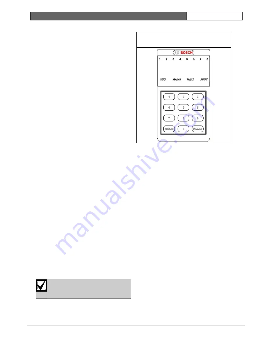
Figure 6:  ICP-CP500PW LED Codepad 

Showing Audible Alarm Buttons 


A codepad Duress Alarm is used as a silent holdup 
alarm when 9 is added to the end of a valid User 
Code being used to disarm the system. If a User 
Code has a priority level that allows arming only, 
that User Code can transmit a Duress Alarm when 
the system is armed. 

A Duress Alarm (Contact ID Event Code 121) is 
useful only if your system reports to a monitoring 
station or pocket pager because domestic reporting 
format cannot decipher the type of alarm that 
occurred. You can disable the codepad Duress Alarm 
Report by programming 0 in Location 394 (refer to 

Section 15.15 Codepad Duress Report

). You can select 

Option 2 in Location 498 to use 3 instead of 9 to 
activate a Duress Alarm (refer to 

Section 18.7 

Consumer Options 3 

on page 83). 

3.8 Codepad 

Panic 

Alarm 

An audible codepad Panic Alarm activates when a 
user presses either [1] and [3] or [STAY] and 
[AWAY] simultaneously.   

Select Option 1 in Location 493 to program the 
codepad Panic Alarm as silent (refer to 

Section 18.2 

System Options 2 

on page 81). To disable the codepad 

Panic Alarm Report, program Locations 405 and 406 
to 0 (refer to 

Section 15.16 Codepad Panic Report 

on 

page 66). A codepad Panic Alarm transmits Contact 
ID Event Code 120 if the system reports to a base 
station receiver. 

Summary of Contents for ICP-CC488

Page 1: ...EN Installation Guide ICP CC488 Control Panel ICP CC488 ...

Page 2: ...the Copyright Act 1968 Cth no part of this publication may be reproduced transmitted modified or stored in any form or by any means without the prior written permission of Bosch Notice of Liability This material is designed for use by tradespeople with expertise in the installation of this product Persons without appropriate expertise should seek assistance before attempting installation While car...

Page 3: ...tor Mode On and Off 25 5 1 8 Walk Test Mode 26 5 1 9 Event Memory Recall Mode 26 5 2 Master Code Functions 27 5 2 1 Arm or Disarm Both Areas at the Same Time 27 5 2 2 Changing and Deleting User Codes 27 5 2 3 Changing and Deleting Remote Radio User Codes 28 5 2 4 Changing Domestic Phone Numbers 28 5 2 5 Change Telco Arm Disarm Sequence 29 5 2 6 Setting STAY Mode 2 Zones 30 5 2 7 Turning Outputs On...

Page 4: ...Access Codes 54 13 1 Installer Code 54 13 2 User Codes 54 13 2 1 User Codes 54 13 3 User Code Priority 55 14 0 Zone Information 56 14 1 Day Alarm Information 56 14 1 1 Day Alarm Resetting 56 14 1 2 Day Alarm Latching 56 14 1 3 Day Alarm Operation 56 14 2 EOL Resistor Value 56 14 3 Zone Programming 58 14 3 1 ICP CC488 Zone Defaults 58 14 3 2 Zone Types 60 14 3 3 Zone Pulse Count 61 14 3 4 Zone Puls...

Page 5: ... 1 85 19 3 2 Partitioning Options 2 85 19 4 Zone Allocations 85 19 4 1 Zone Allocations for Areas 1 and 2 86 19 5 User Code Allocations 86 19 6 Setting Up and Programming Codepads for Partitioning 86 19 6 1 Setting Up the Master Partitioned Codepad as the Main Codepad 87 19 6 2 Setting Up an Area 1 Codepad as the Main Codepad 87 19 6 3 Setting Up an Area 1 Codepad 87 19 6 4 Setting Up an Area 2 Co...

Page 6: ...agram 97 Figure 26 Telecom Connection Diagram for Australia 97 Figure 27 Telecom Connection Diagram for New Zealand 98 Figure 28 Telecom Connection Diagram for China 98 Tables Table 1 Zone Defaults for the ICP CC488 9 Table 2 Zone Types 10 Table 3 Zone Indicators 10 Table 4 STAY Indicator 10 Table 5 AWAY Indicator 10 Table 6 MAINS Indicator 11 Table 7 FAULT indicator 11 Table 8 Audible Indicators ...

Page 7: ...8 Zone Types 60 Table 49 Zone Pulse Count Times 61 Table 50 Zone Options 1 61 Table 51 Keyswitch Zone Options 62 Table 52 Zone Options 2 63 Table 53 Zone Dialer Options 64 Table 54 Output Parameters 70 Table 55 Horn Speaker Beeps 73 Table 56 Event Type Polarities 76 Table 57 Time Base Settings 77 Table 58 Pulsing Time Settings 77 Table 59 One Shot Time Settings 77 Table 60 Strobe Indications for R...

Page 8: ... continue to improve over the years they become very powerful We have addressed the needs of some early first time users who have advanced to true power users while maintaining simplicity of the product and the installation guide 1 1 ICP CC488 Features The ICP CC488 security system uses the latest in microprocessor technology to provide you with useful features and superior reliability and perform...

Page 9: ...ers When programming the telephone numbers for Receiver 1 and Receiver 2 you must program a 0 as a 10 Programming a 0 in the telephone number indicates the end of the dialing sequence Unless otherwise stated program a 0 as a 0 in all locations other than the telephone numbers for Receiver 1 and Receiver 2 and the Call Back Telephone Number If required set the Test Report time Program any other req...

Page 10: ...ast 0 25 sec on 0 25 sec off The zone is in alarm Flashing slow 1 sec on 1 sec off The zone is manually isolated STAY Indicator The STAY indicator lights when the system is armed in STAY Mode 1 or STAY Mode 2 The STAY indicator flashes with the AWAY indicator when you are in Installer s Programming Mode or you are using a Master Code function For more information refer to Section 3 3 to arm the sy...

Page 11: ...the requested operation was denied or aborted One short beep every sec Walk Test Mode is currently active or warning before automatic arming takes place One short beep every 2 sec Telephone Monitor Mode is active One short beep every min There is a system fault to be acknowledged 2 2 ICP CP508LW Eight Zone LCD Codepad Figure 2 ICP CP508LW Eight Zone LCD Codepad The codepad is the communications in...

Page 12: ... indicator lights when the system is disarmed and flashes when a zone becomes unsealed when disarmed The indicator stops flashing when all zones are sealed ON Indicator Zone in Alarm The ON indicator lights when the system is armed and flashes when an alarm occurs The indicator is reset after a valid User Code is entered Audible Indicators The codepad provides a number of audible indications Refer...

Page 13: ...able 6 on page 11 When programming in Installer s Programming Mode or using a Master Code function the MAINS indicator lights to indicate a location value from 10 to 15 The MAINS indicator represents the 10 digit which is added to the value of the lit zone indicator for example if the value programmed in a location is 12 the MAINS and Zone 2 indicators light FAULT indicator The FAULT indicator lig...

Page 14: ...s not permitted If this is the case you seal all zones or manually isolate them before you can arm the system 3 2 Disarming the System from AWAY Mode When you enter the premises after the system is armed in AWAY Mode you must disarm the system from AWAY Mode to disable detection devices that activate the sirens strobe and bell outputs If there was an alarm prior to disarming the system from AWAY M...

Page 15: ...TAY Mode 1 method one 1 Enter your code and press STAY 2 Two beeps sound and the STAY indicator is extinguished The system is now disarmed To disarm the system from STAY Mode 1 method two A flashing zone indicator represents a previous alarm in that zone If this is the case a valid User Code is required to disarm the system using method one To enable method two Option 4 in Location 497 must be ena...

Page 16: ...ethod two A flashing zone indicator represents a previous alarm in that zone If this is the case a valid User Code is required to disarm the system using method one To enable method two Option 4 in Location 497 must be enabled refer to Section 18 6 Consumer Options 2 on page 83 1 Press and hold 0 2 When two beeps sound release the button The STAY indicator is extinguished and the system is disarme...

Page 17: ...ypass Report Contact ID Event Code 570 for each isolated zone when the system is armed A Zone Bypass Restore Report is transmitted when the system is disarmed When you select a 24 Hour Burglary Zone to be isolated a Contact ID Event Code 572 is sent If you select a 24 Hour Fire Zone to be isolated a Contact ID Event Code 571 is sent 3 11 1 Standard Isolating Standard isolating allows any operator ...

Page 18: ...t that occurred 2 RF Low Battery This fault occurs when a wireless zone 1 to 16 reports a low battery condition In Fault Analysis Mode hold down 2 until two beeps sound to light the indicator for the zone that reported the fault 3 Tamper Fail This fault occurs when a zone becomes open circuit In Fault Analysis Mode hold down 3 until two beeps sound to display the zone that reported the fault 4 Sen...

Page 19: ...elephone Line Fault Options 6 EEPROM fail This fault registers when the system detects an internal checksum error Contact your installer if this fault is displayed 7 AUX Power Supply fail This fault occurs when the AUX Power Supply has failed Contact your installer when this fault occurs AC MAINS Failure An AC MAINS supply failure automatically flashes the MAINS indicator If the AC MAINS supply is...

Page 20: ...iver 2 fail 4 0 Remote Radio Transmitter Operations The ICP CC488 Control Panel can be remotely operated using hand held remote radio transmitters You can use either a 2 button or a 4 button hand held transmitter to operate the system Figure 7 RF3332 2 Button Keyfob Transmitter 1 2 3 1 Arm button 2 Disarm button 3 Arm and Disarm buttons Press both buttons at same time for 2 sec to send a Panic ala...

Page 21: ...le Refer to Section 13 3 User Code Priority for more information Before a hand held radio transmitter can operate the control panel you must teach the transmitter s radio code to the control panel Refer to Section 4 3 Changing or Deleting Remote Radio User Codes for more information 4 3 Changing or Deleting Remote Radio User Codes You can use up to eight remote radio hand held transmitters User Co...

Page 22: ...1 1 1 Set the number of days until the first Test Report Section 5 1 2 2 Change domestic telephone numbers Section 5 1 3 3 Change the Telco arm disarm sequence Section 5 1 4 4 Set STAY Mode 2 zones Section 5 1 5 5 Satellite Siren EDMSAT Service Mode Section 5 1 6 6 Turn Telephone Monitor Mode on and off Section 5 1 7 7 Walk Test Mode Section 5 1 8 8 Event Memory Recall Mode Section 5 1 9 5 1 1 Add...

Page 23: ...at 2400 hours as set in Locations 901 to 904 refer to Section 17 16 System Time Example If the repeat interval is set to 7 days but you want the first Test Report to be sent in 2 days enter 1 2 3 4 1 AWAY 2 AWAY 5 1 3 Change Domestic Phone Numbers When the system is set up for domestic dialing this function allows the installer to view and program the telephone numbers the system calls if an alarm...

Page 24: ...arm Dialing Digits Digit Required Number to Program Digit Required Number to Program 0 0 8 8 1 1 9 9 2 2 3 3 STAY 1 4 4 STAY 2 5 5 4 sec pause STAY 3 6 6 break STAY 4 7 7 To program the telco arming sequence 1 Enter the Installer Code and press 3 AWAY Three beeps sound and the STAY and AWAY indicators flash 2 Press 1 AWAY to change the telco arming sequence Three beeps sound If a call forwarding s...

Page 25: ...t to automatically isolate and press STAY The corresponding zone indicator flashes 3 Repeat Step 2 for each zone you want to select As each zone is selected to be isolated the corresponding zone indicator flashes If you make a mistake enter the incorrect zone number and press STAY This zone is no longer selected to be isolated and the zone indicator is extinguished This function does not work on a...

Page 26: ...Y and AWAY indicators are extinguished The system returns to the disarmed state 5 1 9 Event Memory Recall Mode This function allows you to play back the last 40 system events that occurred Event Memory Recall Mode reports all alarms and each arming or disarming of the system and helps with troubleshooting system faults The events are displayed using the codepad indicators To enter Event Memory Rec...

Page 27: ...o Section 19 3 2 Partitioning Options 2 To arm or disarm both areas at the same time Enter your Master Code and press 0 AWAY Two beeps sound and both areas are armed or disarmed from AWAY Mode 5 2 2 Changing and Deleting User Codes This function allows a Master Code holder to change or delete a User Code When using a partitioned ICP CC488 Control Panel the Master Code holder cannot add change or d...

Page 28: ...able 28 3 Press STAY to delete the User Code Two beeps sound and the STAY and AWAY indicators are extinguished 4 Repeat this procedure to delete other remote radio User Codes This function terminates automatically if you do not press a button within 60 sec or if you press AWAY One long beep indicates that the code already exists or that you entered an incorrect user number Table 28 Remote Radio Nu...

Page 29: ... and answering services When this Call Forward option is turned on your telephone does not ring Call Forward No Answer If your telephone is not answered within 20 sec this feature redirects the incoming call to another number anywhere in Australia You can still make outgoing calls Telco Disarming Sequence This option allows you to automatically disable the call forward sequence when you disarm the...

Page 30: ... STAY Mode 2 To arm the system in STAY Mode 2 press and hold 0 until two beeps sound Refer to Section 5 4 3 or Section 3 5 Arming The System in STAY Mode 2 for more information To set STAY Mode 2 zones 1 Enter your Master Code and press 4 AWAY Three beeps sound and the STAY indicator flashes 2 Enter the number of the zone you want to automatically isolate and press STAY The corresponding zone indi...

Page 31: ...nd the STAY and AWAY indicators are extinguished If a long beep sounds an error occurred when you entered the date and time Example To set the date and time for 1st January 2009 at 10 30 PM enter 2 5 8 0 6 AWAY 0 1 0 1 0 9 2 2 3 0 AWAY 5 2 9 Walk Test Mode Walk Test Mode allows you to test detection devices to ensure that they are functioning correctly Before activating Walk Test Mode isolate any ...

Page 32: ...unctions are listed below 5 4 1 Arm the System in AWAY Mode Holding down until two beeps sound arms the system in AWAY Mode This hold down function operates only if you select Option 2 in Location 497 refer to Section 18 6 Consumer Options 2 on page 83 This hold down function does not work if you are using an ICP CP5 Master Partitioned codepad CP500P with a partitioned ICP CC488 Control Panel If y...

Page 33: ...system faults can be detected by the control panel When any of these faults are present the FAULT indicator flashes and the codepad beeps once per min Refer to Section 3 12 Fault Analysis Mode on page 18 for more information on each fault type To determine the type of fault Press and hold 5 until two beeps sound The STAY AWAY and FAULT indicators flash One or more zone indicators 1 to 8 light to i...

Page 34: ...ler Options 1 on page 52 To set the number of rings before the control panel answers refer to Section 11 10 Ring Count on page 51 When both Remote Arming and Upload Download are selected the control panel answers the call expecting the remote computer When this occurs modem negotiating tones sound rather than the remote arming jingle Using this method with a partitioned ICP CC488 Control Panel arm...

Page 35: ...about using Installer s Programming Mode 7 2 Programming with the Programming Key The CC891 Programming Key allows you to store or copy programming information from your control panel After storing information in the programming key you can easily program other ICP CC488 Control Panels with the same programming data You can also use the programming key to back up existing information If you connec...

Page 36: ...rogramming Mode Refer to Section 7 4 2 961 Reset the control panel to factory defaults Refer to Section 7 4 3 962 Copy the control panel memory to the programming key Refer to Section 7 4 4 963 Copy the programming key data to the control panel memory Refer to Section 7 4 5 964 Erase the programming key Refer to Section 7 4 6 965 Set up domestic dialing format Refer to Section 7 4 7 966 Enable dis...

Page 37: ...the Control Panel Memory to the Programming Key This command copies the control panel memory to the programming key You can only use the CC891 Programming Key with the ICP CC488 Control Panel To copy the control panel memory to the programming key 1 Enter the Installer Code the default is 1234 and press to enter Installer s Programming Mode Two beeps sound and the STAY and AWAY indicators flash on...

Page 38: ... format to a one step operation Refer to Section 9 0 Domestic Dialing on page 42 for more information To set up domestic dialing format 1 Enter the Installer Code the default is 1234 and press to enter Installer s Programming Mode Two beeps sound and the STAY and AWAY indicators flash on the remote codepad to indicate you entered Installer s Programming Mode The remote codepad displays the data st...

Page 39: ... various control panels use the same PCB The codepad displays 8 to indicate the control panel software ICP CC488 To display the control panel type or software version number 1 Enter the Installer Code the default is 1234 and press to enter Installer s Programming Mode If you are using the remote codepad the STAY and AWAY indicators flash to indicate you entered Installer s Programming Mode 2 Enter...

Page 40: ... button The default button is located at the top of the PCB next to the PROGRAMMING KEY socket 3 Reconnect the AC MAINS supply to the control panel 4 Wait 3 to 5 sec and release the default button 5 Enter 2 5 8 0 to disarm the system using the default Master Code The control panel default factory settings are restored If the option to restore the default control panel settings is disabled using Lo...

Page 41: ...computer to make contact It allows the customer to initiate a modem call by holding down 6 8 1 3 Remote Connection with Callback Verification Remote connect with callback verification offers the highest degree of data security by incorporating a two level security check The first level is provided because the Installer Code and the Subscriber ID Number must match those of the control panel The sec...

Page 42: ... Receiver 2 is not available for domestic dialing format Refer to Section 9 2 Setting Up and Programming Domestic Reporting on page 43 for more information 9 1 Domestic Dialing Function When the control panel is activated into alarm it dials the first programmed telephone number If a busy or engaged tone is detected the control panel hangs up and dials the sec telephone number if one is programmed...

Page 43: ...mber 7 Repeat Step 6 for each additional phone number 8 After the last digit of the last telephone number press AWAY to exit from this mode Table 38 Domestic Dialing Digits Digit Required Number to Program Digit Required Number to Program 0 0 8 8 1 1 9 9 2 2 3 3 STAY 1 4 4 STAY 2 5 5 4 sec pause STAY 3 6 6 break STAY 4 7 7 15 STAY 5 Example To program two separate telephone numbers 9672 1777 and 9...

Page 44: ...tention to the Event Code Refer to Section 10 1 3 Alarm Link Options for more information about the ICP CC488 Point ID Codes 10 1 3 Point ID Codes Table 43 on page 46 shows the different Point ID Codes and Event Codes transmitted to the base station receiver when using Contact ID Reporting Format All Event Codes are fixed The control panel always transmits the same code because there are no progra...

Page 45: ...n Locations 000 to 015 refer to Section 11 1 Primary Telephone Number for Receiver 1 and Receiver 2 on page 49 2 Program the Subscriber ID Number in Locations 034 to 039 refer to Section 11 5 Subscriber ID Number for Receiver 1 and Receiver 2 on page 50 3 Select the Pager Handshake option 5 in Location 032 refer to Section 11 3 Handshake Tone for Receiver 1 and Receiver 2 on page 49 4 Program the ...

Page 46: ...ific 1 to 16 Codepad Duress 121 Duress Alarm 15 15 041 Codepad Panic 120 Panic Alarm 15 16 046 Codepad Fire 110 Fire Alarm 15 17 045 Codepad Medical 100 Medical Alarm 15 18 042 Code Retry Limit Exceeded 421 Access Denied 15 26 044 Test Report Automatic 602 Test Report 15 28 047 Test Report After Siren Reset 602 Test Report 18 5 Zone Specific 1 to 8 Sensor Self Test Failure 307 Sensor Watch 15 5 Zo...

Page 47: ... 08 F01U089457 02 Figure 9 Basic Pager Display 1 Subscriber ID number 2 Zone status 3 System status 4 0 Zone Normal 1 Alarm 2 Manually Isolated 3 Auto Isolated 5 8 Disarmed 9 Armed 6 0 Normal 1 Panic Duress 2 Fire Alarm 3 Medical Alarm 7 0 AC Normal 1 AC Failure 8 0 System Normal 1 System Fault ...

Page 48: ...S supply The fourth digit indicates whether a system fault occurred at the control panel refer Section 3 12 Fault Analysis Mode on page 18 for more information 11 0 Dialer Information This section outlines the programming information required for the ICP CC488 Control Panel when communicating with a base station receiver These parameters specify the telephone numbers to call transmission formats h...

Page 49: ... calls per alarm Contact your monitoring station or pager company for the correct telephone numbers before you program these locations When Receiver 1 or 2 is set up for domestic reporting telephone numbers programmed into these locations are ignored Refer to Section 5 1 3 Change Domestic Phone Numbers on page 23 using the Installer Code function or Section 5 2 4 Changing Domestic Phone Numbers on...

Page 50: ...on beeps is determined by the value programmed in Location 039 Receiver 1 and Location 079 Receiver 2 This value allows the identification of up to 15 different control panels that call the same telephone number Example To program the Subscriber ID Number as 4729 program the six locations as 0 0 4 7 2 9 11 6 Dialing Format Location 080 1 Australian DTMF 5 digits sec 2 Australian decadic 3 Alternat...

Page 51: ...e and must be set to Waiting for an Incoming Call The Call Back Telephone Number is also required if Remote Connection with Callback Verification is required refer to Section 8 1 3 on page 41 Refer to Section 8 0 Alarm Link Software on page 40 for more information 11 10 Ring Count Location 175 Default 8 0 Panel does not answer 1 to 13 Number of rings until panel answers 14 Answering machine bypass...

Page 52: ...once per min if the control panel detects that the telephone line is disconnected Refer to Section 3 13 Fault Descriptions on page 18 for more information 2 Sound Alarm When System Is Armed You must also select Option 1 to use this option If the control panel detects that the telephone line is disconnected when the system is armed the horn speaker bell and strobe outputs are activated If only one ...

Page 53: ...Section 15 13 Open Close Reports on page 65 for this option to work For a partitioned ICP CC488 Control Panel an Open Close Report is sent only for the area in which the alarm occurred If the system is disarmed when an alarm occurs only a Closing Report is sent the next time the system is armed A User Code with a priority set to Always Send Open Close Reports overrides this feature Open Close Repo...

Page 54: ...efer to Section 5 1 Installer Code Functions on page 22 for more information Refer to Section 7 1 Programming with the Remote Codepad on page 34 for more information on programming the system 13 2 User Codes The purpose of User Codes is to arm and disarm the system and to perform other specific functions as described in Section 5 2 Master Code Functions 26 A Master Code holder can change or delete...

Page 55: ...port 4 Arm disarm and code to isolate 6 Arm disarm code to isolate and Open Close Reports 8 Arm disarm and Master Code functions 10 Arm disarm Master Code functions and Open Close Reports 12 Arm disarm Master Code functions and code to isolate 14 Arm disarm Master Code functions code to isolate and Open Close Reports Arm Disarm The user can arm and disarm the system A Closing Report is sent only a...

Page 56: ... 14 1 2 Day Alarm Latching An output that is programmed for Day Alarm Latching operates when a zone programmed for Day Alarm is activated The zone indicator and the latching output resets when AWAY is pressed This occurs only when the system is disarmed Refer to Output Event Type 0 15 Day Alarm Latching on page 72 for more information 14 1 3 Day Alarm Operation If a zone is programmed for Day Alar...

Page 57: ...en using split EOL resistors refer to Figure 12 and Figure 13 on pages 57 and 58 for information on how to connect N O contacts Figure 10 Split EOL Resistors Using N C Contacts 1 9 2 9 4 9 3 9 5 10 8 10 6 10 7 10 1 Zone 1 2 Zone 2 3 Zone 3 4 Zone 4 5 Zone 5 6 Zone 6 7 Zone 7 8 Zone 8 9 3K3 10 6K8 Figure 11 Split EOL Resistors with Tamper Circuit 1 4 5 6 3 2 1 4 1 Tamper 2 Zone 1 3K3 3 Zone 5 6K8 4...

Page 58: ... Zone Dialer Options The Zone Report Code determines if the control panel sends Alarm Reports for the zone Refer to Section 14 3 8 Zone Report Code on page 64 for more information The Zone Dialer Options location enables you to specify how a zone reports to a base station receiver Refer to Section 14 3 9 Zone Dialer Options on page 64 for more information 14 3 1 ICP CC488 Zone Defaults Location 26...

Page 59: ...ne Pulse Count 338 0 Zone Pulse Count Time 339 0 Zone Options 1 340 1 Zone Options 2 341 14 Report Code 342 1 Dialer Options 343 1 Zone 12 Default Instant Zone Type 344 15 Zone Pulse Count 345 0 Zone Pulse Count Time 346 0 Zone Options 1 347 1 Zone Options 2 348 14 Report Code 349 1 Dialer Options 350 1 Location 267 to 378 continued Location Default Zone 13 Default Instant Zone Type 351 15 Zone Pu...

Page 60: ... Zone is not restored when the system is disarmed a Zone Restore Report is automatically sent to the receiving party 6 24 Hour Medical Zone A 24 Hour Medical Zone Contact ID Event Code 100 is always ready to activate the dialer horn speaker bell and strobe whether the system is armed or disarmed A Medical Report is transmitted to the base station receiver A 24 Hour Medical Zone does not send a Res...

Page 61: ...s 8 to 15 Refer to Section 14 3 4 Zone Pulse Count Time for more information Any zone that registers one activate pulse automatically increments any other zone pulse count that already registered at least one activate pulse during its respective time To enable this feature select Option 4 in Location 494 refer to Section 18 3 System Options 3 on page 81 24 Hour Zones will receive all handover puls...

Page 62: ...Reports on page 78 This value specifies how many 24 hour periods a zone can remain continuously sealed before it registers as a Sensor Watch fault The number of hours required to fulfill these 24 hour periods is calculated only when the system is disarmed Every time the system is armed in the AWAY Mode STAY Mode 1 or STAY Mode 2 the Sensor Watch Timer pauses its count The Sensor Watch Timer contin...

Page 63: ...eyswitch input Arming the system in STAY Mode 1 or STAY Mode 2 or arming and disarming the system from AWAY Mode is not permitted from the Keyswitch Zone Figure 14 Wiring Diagram for Keyswitch Zone 1 2 1 EOL 2 Keyswitch Momentary Toggle Figure 15 Wiring Diagram for Keyswitch Zone Using Split EOL with Tamper 1 2 1 EOL 2 Keyswitch Momentary Toggle 14 3 7 Zone Options 2 This location has four program...

Page 64: ...t siren Only alarms activated from zone inputs can decrement the Swinger Shutdown Counter Alarms such as Codepad Panic Access Denied and other system alarms do not affect the Swinger Shutdown Count When the sirens are operating the Swinger Shutdown Counter is decremented only by the first zone that activated the alarm Any other zones activated during Siren Run Time do not affect the counter When t...

Page 65: ...ors 3K3 6K8 with tamper 1K becomes open circuit To enable Zone Tamper and Zone Tamper Restore Reports program the two locations with any digit from 1 to 15 15 2 Zone Status Walk Test Report Location 383 to 384 Location Default Walk Test Report 383 0 Walk Test Restore Report 384 0 A Walk Test Report Contact ID Event Code 607 is sent when either the Installer or Master Code holder activates Walk Tes...

Page 66: ...store code and is global for all zones A zone Restore Report is sent only to the receiving party to which the zone is allocated for example Receiver 1 or Receiver 2 15 7 Zone Status Reporting Options Location 392 0 No zone status reports allowed 1 Report to Receiver 1 2 Report to Receiver 2 4 Report to both Receiver 1 and Receiver 2 8 Report to Receiver 2 only if Receiver 1 fails This location is ...

Page 67: ...ns 2 on page 53 To enable Open and Close Reports only after a previous alarm select Option 1 in Location 178 If Open and Close Reports are not required program Locations 401 and 402 as 0 A partitioned ICP CC488 Control Panel sends Open Close Reports with Contact ID Event Code 402 15 14 Open Close Reporting Options Location 403 0 No Open Close Reports allowed 1 Report to Receiver 1 2 Report to Rece...

Page 68: ... 8 Report to Receiver 2 only if Receiver 1 fails Location 411 is set by default to report only to Receiver 1 You can select whether Codepad Alarm Reports are sent to Receiver 1 Receiver 2 or both Receiver 2 only when Receiver 1 fails or no reporting 15 20 System Status AUX Power Supply Fail Report Location 412 to 413 Location Default Tens digit 412 10 Units digit 413 3 A System Trouble Report Cont...

Page 69: ...he number of times an invalid User Code can be entered in an attempt to operate the system Location 424 sets the number of incorrect code attempts that causes an alarm When the number of incorrect code attempts equals the number programmed in this location the system performs these actions Activates the sirens internal screamers and strobes connected to the control panel Select Option 8 in Locatio...

Page 70: ...nd internal screamer Programmable outputs require four parameters to operate correctly Table 54 Output Parameters Parameter Description Event Type The Event Type specifies when an output is activated The Output Event Types are listed in Section 16 2 on page 71 Enter the code for the Output Event Type into the two corresponding locations for the output Polarity Polarity determines whether the outpu...

Page 71: ...et when the system is armed If the system is partitioned this output operates when both areas are disarmed 0 3 Armed in STAY Mode This output operates when the system is armed in STAY Mode 1 or STAY Mode 2 The output is reset when the system is disarmed If the system is partitioned this output operates when either area is armed in STAY Mode 1 0 4 Armed in AWAY Mode This output operates when the sy...

Page 72: ...one to which the zone is allocated or pressing AWAY on a CP5 Master Partitioned Codepad does not reset the output You can reset only this output on the area codepad to which the zone is allocated 1 0 Day Alarm Enabled This output operates when Day Alarm is enabled The output is reset when Day Alarm is turned off Refer to Section 14 1 Day Alarm Information on page 56 for programming zones to operat...

Page 73: ...e 55 Table 55 Horn Speaker Beeps No of Beeps System Status 1 System disarmed 2 System armed in AWAY Mode 3 System armed in STAY Mode 1 1 14 Horn Speaker Output 1 Only This output operates only on Output 1 Use this output for one or two 8 Ω horn speakers Refer to Section 17 9 Siren Run Time and Section 17 10 Siren Sound Rate to program the speaker To enable monitoring of the horn speaker select Opt...

Page 74: ...em Options 1 on page 80 this output does not operate and arms the system in STAY Mode 1 only 2 13 Radio Control Output 1 Not in AWAY Mode This output operates when the DOOR button on the 4 channel hand held transmitter is activated when the system is disarmed or armed in STAY Mode 1 or STAY Mode 2 The output does not operate when the system is armed in AWAY Mode 2 14 Radio Control Output 2 Not in ...

Page 75: ...onding area registers an alarm These outputs are reset when a valid User Code is entered Example Zone 1 is allocated to Area 1 If Zone 1 registers an alarm Output Event Type 5 2 operates The output is reset when a valid User Code assigned to Area 1 is entered 5 6 Area 1 Is Armed 5 7 Area 2 Is Armed These two outputs operate when their corresponding area are armed in AWAY Mode or STAY Mode 1 The ou...

Page 76: ...g expires This one shot time setting always runs its full duration and cannot be manually reset 4 Normally Open One Shot Low with Reactivate This one shot polarity is normally open circuit and switches to 0 V when the event occurs Every time the event occurs it restarts the one shot timer The output switches back to open circuit when the one shot time expires This one shot time setting always runs...

Page 77: ...ity When you program outputs to pulse you can set both the On and Off times You can program one shot polarities to operate from 200 ms to 99 hours The maximum value you can program in the two multiplier locations is 9 9 Table 57 Time Base Settings Option Description 1 200 ms 2 1 sec 3 1 min 4 1 hour You can only set the time base settings to one of the values listed in Table 57 on page 77 The mult...

Page 78: ... of Exit Time when arming in STAY Mode 1 or STAY Mode 2 17 5 Entry Guard Timer for STAY Mode Location 472 to 473 Location Default Increments of 1 sec 0 sec to 15 sec 472 0 Increments of 16 sec 0 sec to 240 sec 473 0 Entry Guard Timer for STAY Mode is the delay time used for all zones except 24 Hour Burglary and 24 Hour Fire Zones when the system is armed in STAY Mode 1 or STAY Mode 2 All zones inc...

Page 79: ...The codepad beeps once every second until the Pre Alert Timer expires the system then automatically arms itself in AWAY Mode If you want the system to automatically arm in STAY Mode 1 enable Option 4 in Location 496 refer to Section 18 5 Consumer Options 1 on page 82 After the control panel is automatically armed in AWAY Mode or STAY Mode 1 Exit Time starts If a valid User Code is entered during t...

Page 80: ... day of the month MM is the month of the year YY is the year HH is the hour of the day and MM minute of the day and press AWAY Use 24 00 hour format when programming the hour of the day Two beeps sound and the STAY and AWAY indicators are extinguished If a long beep sounds there was an error when you entered the date and time Example To set the date and time for the 1st January 2004 at 10 30 PM en...

Page 81: ... 17 Codepad Fire Report on page 66 4 Codepad Medical To Be Silent If this option is selected a Codepad Medical Alarm does not operate the horn speaker the bell or the strobe outputs If this option is not selected all three outputs operate after a Codepad Medical Alarm is activated when a user presses 7 and 9 at the same time on the remote codepad Selecting this option does not affect the operation...

Page 82: ...ntrol panel keeps its current armed status in non volatile memory If the control panel is restarted due to a power failure the control panel returns to being armed or disarmed as it was before the power failed Example If the system is disarmed when the system is powered down the system returns to the disarmed state when the system is powered back up 4 Internal Crystal To Keep Time If this option i...

Page 83: ...e 32 for more information 8 Alarm Memory Reset on Disarm If this option is selected the alarm events memory clears from the remote codepad when the system is disarmed If this option is not selected the system must be armed and disarmed again to clear alarm memory from the remote codepad 18 7 Consumer Options 3 Location 498 1 Codepad fault beeps allowed 2 Use digit 3 for Codepad Duress Alarm instea...

Page 84: ... of a CP5 Area Addressable CP500A codepad in a partitioned system are exactly the same as the CP5 Eight Zone LED codepad except that the commands issued from the codepad affect only the area to which the codepad is allocated Refer to Section 3 0 System Operations on page 14 for more information Example If the codepad is allocated to Area 2 only User Codes that are allocated to Area 2 can operate t...

Page 85: ...aker strobe bell or EDMSAT outputs while in alarm This option does not allow a User Code allocated to one area to disarm another area 8 Master Codepad To Display AUX Indicator When Online If this option is selected the AUX indicator on the CP5 Master Partitioned CP500P codepad lights when the control panel seizes the telephone line to send a report The AUX indicator is extinguished when the teleph...

Page 86: ...Programming the same zone into more than one area specifies that zone as a common zone Figure 18 Area 1 Codepad Display Area 1 Zone Allocations Locations 502 to 509 1 2 3 4 0 0 0 0 Figure 19 Area 2 Codepad Display Area 2 Zone Allocations Locations 510 to 517 1 0 0 0 5 6 7 8 19 5 User Code Allocations Location 534 to 549 Location Default User Code 1 534 0 User Code 2 535 0 User Code 3 536 0 User Co...

Page 87: ...depad to the main codepad terminals CP CP and CLK and connect the DATA terminal to one of the outputs programmed as 6 0 Area 1 Codepad Data refer to page 75 Set DIP switch 1 on the back of the Area 1 codepad to the ON position refer to Figure 20 on page 87 19 6 4 Setting Up an Area 2 Codepad If you want a separate area codepad only for Area 2 connect the Area 2 Codepad to the main codepad terminal...

Page 88: ...ge 75 Figure 22 Connections for Two CP 5 Area Addressable Codepads 1 Data 2 CLK 3 12 V 4 GND 5 Area 1 Codepad 6 Area 2 Codepad 20 0 RF Information 20 1 RF Option Bit Location 599 Default 0 1 Sound siren on RF receiver fail 2 Sound siren on RF receiver tamper jamming 4 Unseal zone that fails supervision if supervision enabled 8 Enable RF jamming monitoring 1 Sound Siren on RF Receiver Fail If this ...

Page 89: ...es 1 to 8 to any of the 16 zones on the control panel You cannot map more than one RF wireless device to the same zone Refer to Section 20 4 Default RF Device Mapping Devices 9 to 16 to map RF wireless devices 9 to 16 By default RF devices 1 to 8 are mapped separately to each of the eight zones that is Device 1 is mapped to Zone 1 Device 2 to Zone 2 and so on Locations 616 to 623 and locations 624...

Page 90: ...w you to view the received signal strength for RF wireless Devices 9 to 16 Location 809 displays the signal strength of Device 9 Location 810 displays the signal strength of Device 10 and so on The signal strength is measured from 0 lowest to 8 highest 21 0 Optional Equipment Bosch Security Systems Inc manufactures a number of accessories that can be used in conjunction with the ICP CC488 Control ...

Page 91: ...P508LW Eight Zone LCD Codepad This codepad operates with the ICP CC488 control panels This codepad has a fixed icon display and provides indications for up to eight zones This codepad cannot be used with the ICP CC488 Control Panel 21 8 ICP CP500AW Eight Zone Area Addressable Codepad This codepad operates with a partitioned ICP CC488 Control Panel This codepad has a DIP switch on the back to selec...

Page 92: ...rogramming options You can use them for a variety of functions with considerable flexibility All outputs have a common 12 VDC terminal and each output can sink up to 400 mA By default Output 1 operates a horn speaker This group of terminals is protected by the solid state IPS system which provides considerable tolerance to abuse or incorrect wiring Each output is open collector and does not source...

Page 93: ... electric beams reed switches and vibration sensors dialer An electronic device that uses tones or pulses to dial an electronic receiver such as a monitoring station mobile phone or pocket pager It uses the public switched telephone network to send alarm or supervisory signals disarmed A system status that does not accept alarms except for 24 hour zones dual reporting Reporting that allows your co...

Page 94: ...t violated and the zone indicator is not lit that is a reed switch is closed or a detector is on standby waiting for an intrusion sensor watch A feature that allows the control panel to recognize when detection devices might have stopped working Sensor watch monitors the operation of a zone over a programmed time period silent alarm An alarm that sounds only at a remote location and gives no obvio...

Page 95: ... 5 Yellow Internal phone line 3 and 4 Not used 2 Black Telecom line street 1 Green Internal phone line 3 Zone 1 4 Zone 5 5 Zone 2 6 Zone 6 7 Power to external equipment 12 V 400 mA 8 PIR 9 Zone 8 10 Zone 4 11 Zone 7 12 Zone 3 13 Piezo siren 14 Smoke detector 15 Strobe 16 Horn speaker 17 Codepad 18 Yellow 19 Green 20 Red 21 Black 22 Battery 23 18 VAC 1 3 A plug pack TF008 24 Link between 12 V and C...

Page 96: ... Overlay 1 Socket for telecom lead connect 2 Termination for phone line OUT internal phone line IN Telecom line street 3 Receiver interface connection 4 Zone termination strip 5 Output termination strip 6 Battery input 7 Plug pack input Bosch TF008 8 Relay contact select 9 Default switch 10 Programming key 11 Auxiliary Module direct link cable ...

Page 97: ...LED in the centre of the module lights Operation The LED shows the status of the DSRF RF Receiver LED On the module is functioning normally LED Off a power failure occurred or the module is not wired correctly LED turns off momentarily the module acknowledged receiving an RF signal from a remote RF device Figure 26 Telecom Connection Diagram for Australia 1 2 3 9 7 4 5 6 10 2 3 9 7 8 1 Control pan...

Page 98: ...e 7 black telecom line street green internal phone line red telecom line street yellow internal phone line 8 Green wire 9 Yellow wire Figure 28 Telecom Connection Diagram for China 1 2 3 4 5 6 7 8 10 9 1 Control panel 2 Red wire 3 Black wire 4 4P4C plug top view 5 RJ12 plug top view 6 Telecom line 7 Internal phones 8 Rear view of telephone plate green internal phone line black telecom line street ...

Page 99: ...n between the would be burglar and the control panel Anyone with a little knowledge of alarm systems can trick the dialer that it is communicating to a base station and clear the alarm signal It is pretty frightening when the control panel you use and recommend to your customers is supposed to have anti jamming At Bosch Security Systems Inc we take anti jamming very seriously and have devoted a gr...

Page 100: ...ng As you can see using the ICP CC488 Control Panel saves you money saves your customer money and helps to conserve our natural resources In fact the only organization that doesn t like this feature is Telecom 24 0 Specifications 24 1 Warranty Statement Bosch Security Systems Inc warrants this product to be free from defects in material and workmanship for a period of three years from the date of ...

Page 101: ...ustomers In the event of any problem with this device disconnect the system battery AC MAINS supply and the telephone line The user must arrange with the supplier of the device for the necessary repairs If the matter is reported to Telecom as a wiring fault and the fault is proven to be due to this product a call out charge will be incurred 24 5 A Tick The ICP CC488 Control Panel is designed to co...

Page 102: ... 0 0 0 0 0 Callback Telephone Number Location 159 to 174 Refer to page 51 Default 0 0 0 0 0 0 0 0 0 0 0 0 0 0 0 0 Ring Count Location 175 Refer to page 51 Default 8 0 Panel will not answer 1 to 13 Number of rings until panel answers 14 Answering machine bypass 2 15 Answering machine bypass 1 Telephone Line Fault Options Location 176 Refer to page 52 Default 0 1 Display FAULT indicator if telephone...

Page 103: ...15 2 Radio Code 14 Locations 250 to 254 Default 15 15 15 15 2 Radio Code 15 Locations 255 to 259 Default 15 15 15 15 2 Radio Code 16 Locations 260 to 264 Default 15 15 15 15 2 User Code Priority Levels Priority Description 0 Arm disarm 1 Arm only 2 Arm disarm and Open Close Reports 3 Arm only and Close Report 4 Arm disarm and code to isolate 6 Arm disarm code to isolate and Open Close Reports 8 Ar...

Page 104: ...ontains seven locations The first three locations determine how the zone operates Zone Type Zone Pulse Count Zone Pulse Count Time The next two locations contain zone options Zone Options 1 Zone Options 2 The last two locations contain reporting information Report Code Dialer Options Zone Types These are the zone types available Zone Type Description 0 Instant 1 Handover 2 Delay 1 3 Delay 2 4 Rese...

Page 105: ... 389 to 390 Refer to page 66 Default 4 5 Location 389 Sensor Watch Report Location 390 Sensor Watch Restore Report Zone Status Alarm Restore Code Location 391 Refer to page 66 Default 14 Zone Status Reporting Options Location 392 Refer to page 66 0 No report required 1 Receiver 1 2 Receiver 2 4 Receiver 1 and 2 8 Receiver 2 only when Receiver 1 fails RF Supervision Time Location 393 Refer to page ...

Page 106: ...en Receiver 1 fails Test Reporting Time Location 428 to 434 Refer to page 69 Default 0 0 0 0 7 1 0 Location 428 Hour of the day tens digit Location 429 Hour of the day units digit Location 430 Minute of the day tens digit Location 431 Minute of the day units digit Location 432 Test Report code tens digit Location 433 Test Report code units digit Location 434 Repeat interval in days Test Reporting ...

Page 107: ...ation 487 Hour of the day units digit Location 488 Minute of the day tens digit Location 489 Minute of the day units digit Kiss Off Wait Time Location 490 Refer to page 80 Default 3 Location 490 Increments of 500 ms Speaker Beep Volume Location 491 Refer to page 80 Default 13 0 No beeps 15 Loudest beeps System Options 1 Location 492 Refer to page 80 1 Bosch Security Systems Inc smart lockout allow...

Page 108: ...cation 512 Area 2 Zone 3 indicator Location 513 Area 2 Zone 4 indicator Location 514 Area 2 Zone 5 indicator Location 515 Area 2 Zone 6 indicator Location 516 Area 2 Zone 7 indicator Location 517 Area 2 Zone 8 indicator 0 1 Not mapped for this LED This LED used a zone is mapped to it Zone Allocations for Area 1 and Area 2 Location 518 to 533 Refer to page 85 Default 0 0 0 0 0 0 0 0 Location 518 Ar...

Page 109: ...23 07 0 15 Mapping RF device to zone 1 16 RF Device Mapping Devices 9 to 16 Location 624 to 631 Refer to page 89 Location Default Map RF Device 9 to Zone 1 to 16 624 08 Map RF Device 10 to Zone 1 to 16 625 09 Map RF Device 11 to Zone 1 to 16 626 10 Map RF Device 12 to Zone 1 to 16 627 11 Map RF Device 13 to Zone 1 to 16 628 12 Map RF Device 14 to Zone 1 to 16 629 13 Map RF Device 15 to Zone 1 to 1...

Page 110: ...0 4 Russian Federation 4 4 Albania 6 5 6 5 St Lucia 6 5 Brazil 0 5 Saudi Arabia 4 5 Andorra 6 5 Grenada 6 5 Samoa Eastern 6 5 Bulgaria 0 6 Serbia and Montenegro 4 6 Angola 6 5 Guatemala 6 5 San Marino 6 5 Canada 0 7 Singapore 4 7 Antigua and Barbuda 6 5 Guinea 6 5 Sao Tome and Principe 6 5 China 0 8 Slovakia 4 8 Azerbaijan 6 5 Guyana 6 5 Saint Vincent 6 5 Colombia 0 9 Slovenia 4 9 Bahamas 6 5 Hait...

Page 111: ...Mauritania 6 5 Lithuania 2 9 Oman 6 2 Congo 6 5 Mauritius 6 5 Luxembourg 3 0 Pakistan 6 2 Costa Rica 6 5 Micronesia 6 5 Macedonia 3 1 Qatar 6 2 Cuba 6 5 Monaco 6 5 Malaysia 3 2 Syria 6 2 Djibouti 6 5 Mongolia 6 5 Malta 3 3 Ukraine 6 2 Dominica Rep 6 5 Mozambique 6 5 Mexico 3 4 East Timor 6 5 Namibia 6 5 Netherlands 3 5 Algeria 6 3 Ecuador 6 5 Nauru 6 5 New Zealand 3 6 Bahrain 6 3 El Salvador 6 5 N...

Page 112: ...ICP CC488 Installation Guide Index EN 112 Bosch Security Systems Inc 12 08 F01U089457 02 Notes ...

Page 113: ...ire 17 81 Codepad Fire To Be Silent 81 Codepad Indicators AWAY 10 AWAY Indicator 11 FAULT 11 13 FAULT Indicator 12 MAINS 11 MAINS Indicator 12 Off Indicator 12 On Indicator 12 STAY 10 STAY Indicator 11 System Disarmed 12 Zone Indicators 11 Codepad Medical 17 81 Codepad Medical To Be Silent 81 Codepad Panic 16 81 Codepad Panic To Be Silent 81 Command 959 Test Programming Key 36 Command 960 Exit Ins...

Page 114: ...Code 54 Installer Code Function Change Telco Arm Disarm Sequence 24 29 Setting STAY Mode 2 Zones 25 30 Telephone Monitor Mode 25 Installer s Programming Commands 959 Test Programming Key 36 960 Exit Installer s Programming Mode 37 961 Reset Control Panel Back To Factory Default 37 965 Set Up Domestic Dialing 38 966 Automatic Stepping Of Locations 38 999 Display Panel Type Software Version Number 3...

Page 115: ...setting 72 Exit Warning 71 Exit Warning Finished 71 Exit Warning With All Zones Sealed Or Entry Warning 71 Fire Alarm Latching 73 Fire Alarm Resetting 73 Fire Alarm Verification 74 Global Chime 75 Horn Speaker 73 Horn Speaker Monitor Fail 72 Kiss Off After Exit Time 71 Kiss Off Received 72 Low Battery 72 Mimic System Fault 73 Mimic Zone 1 75 Mimic Zone 2 75 Mimic Zone 3 75 Mimic Zone 4 75 Mimic Zo...

Page 116: ...8 62 Smart Watch 80 STAY Indicator 10 11 STAY Indicator To Display Day Alarm Status 83 STAY Mode 1 Arming 14 32 STAY Mode 2 Arming 15 32 Setting Zones 25 30 Strobe Test 33 System Disarmed 12 System Operations Arming In AWAY Mode 14 Arming In STAY Mode 1 14 Arming In STAY Mode 2 15 Disarming From AWAY Mode 14 System Options 1 EDM Smart Lockout 80 System Options 2 Access Denied To Be Silent 81 Codep...

Page 117: ...rouble 65 Zone Bypass 65 Zone Indicators 11 Zone Options 1 Lockout Siren Dialer 61 Sensor Watch 62 Zone Options 2 Isolate In STAY Mode 1 63 Zone Isolation Allowed 63 Zone Restore Report 64 Zone Reporting Information Zone Restore Code 66 Zone Types Chime Zone 61 Delay 1 Zone 60 Delay 2 Zone 60 Handover Zone 60 Instant Zone 60 ...

Page 118: ... 2008 Bosch Security Systems Inc F01U089457 02 Bosch Security Systems Inc 130 Perinton Parkway Fairport NY 14450 9199 USA www boschsecurity com ...

Reviews: