background image

76

en | Default Configuration

DiBos/DiBos Micro

F.01U.033.308 | V7 | 2009.09

Installation Guide

Bosch Sicherheitssysteme GmbH

6.5.4

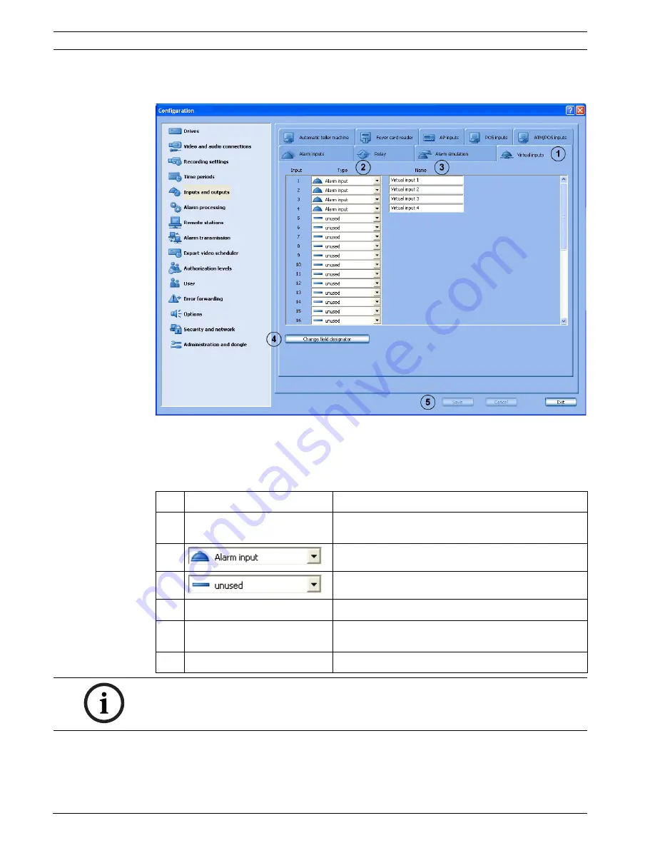
Configuring Virtual Inputs

Inputs and outputs

 menu > 

Virtual inputs

 tab

Virtual inputs are inputs that are controlled via the browser interface or by a piece of 

software. They offer the same functionality as the other inputs in the system.

The virtual inputs can be used to execute jobs in the video system, for example for alarm 

transmission or export video. There are 32 virtual inputs available.

1

Virtual inputs

Click the tab.

2

Type

Click the down arrow in the column and select 

whether a virtual input is to be configured or not.

Input is to be used as virtual input.

Input is not to be used as virtual input.

3

Name

Place the cursor in the column and enter the name.

4

Change field designator

Click the button. A dialog box opens. Edit the 

designation of the additional data as necessary.

5

Save

The entries are saved.

NOTICE! 

It is not necessary to log on to gain access to the virtual inputs interface.

Summary of Contents for DiBos

Page 1: ...DiBos DiBos Micro en Installation Guide ...

Page 2: ......

Page 3: ... I O Card for DiBos 24 3 2 DiBos micro 25 3 2 1 DiBos micro Front View 25 3 2 2 DiBos micro Rear View 26 3 2 3 Grabber Card for DiBos micro 27 3 2 4 I O Card for DiBos micro 28 4 Quick Installation 30 5 Quick Configuration 31 5 1 General Settings 31 5 2 Creating a User 33 5 3 Setting up the Network 34 5 4 Specifying Cameras 36 5 5 Assigning Time Profiles 37 5 6 Setting Up Recording 38 6 Default Co...

Page 4: ...uring Alarm Processing 90 6 7 Configuring Remote Stations 94 6 8 Configuring Alarm Transmission 97 6 9 Configuring the Export Video Scheduler 100 6 10 Creating Authorization Levels 102 6 11 Configuring Users 107 6 12 Configuring Error Forwarding 109 6 13 Configuring Options 111 6 13 1 MIB List for SNMP 114 6 13 2 Notification via SNMP 115 6 13 3 Configuring Automatic Alarm Recording 116 6 14 Confi...

Page 5: ...P 143 9 11 1 General 143 9 11 2 Connecting to NZ 500 20 mA Video System NZ 500 145 9 11 3 Connecting to BZ 500 20 mA 145 9 11 4 Connecting to AZ 1010 NZ 1008 146 9 11 5 Connecting to NZ 1012 147 9 11 6 Connecting to NZ 1060 148 9 11 7 Connecting to UEZ 1000 20 mA 149 9 11 8 Connecting to UEZ 2000 20 mA 149 9 11 9 Connecting to UGM 2020 150 10 Troubleshooting and Checks 151 10 1 Troubleshooting 151...

Page 6: ...6 en Table of Contents DiBos DiBos Micro F 01U 033 308 V7 2009 09 Installation Guide Bosch Sicherheitssysteme GmbH ...

Page 7: ...spray cans 6 Service Do not attempt to service the device yourself You may be exposed to high electrical voltages or other hazards if you open or remove covers Servicing must be carried out by qualified maintenance personnel 7 Damage requiring service Unplug the device from the mains power supply and arrange for the device to be serviced by qualified personnel if The mains cable or mains plug is d...

Page 8: ...re that the cable system is grounded Only for models available in the USA Section 810 of the National Electrical Code ANSI NFPA No 70 1981 contains information on the correct grounding of the mounting coax grounding at a discharge device the size of the ground conductors the location of the discharge device connection to discharge electrodes and requirements regarding the discharge electrodes 12 G...

Page 9: ...t not be exceeded Mechanical load When installing the device in a rack beware of hazards that may arise due to unequal mechanical load WARNING Interruption of mains supply Voltage is applied as soon as the mains plug is inserted into the mains socket However for devices with a mains switch the device is only ready for operation when the mains switch ON OFF is in the ON position When the mains plug...

Page 10: ...sch product has been developed and manufactured using high quality materials and components that can be reused This symbol means that electronic and electrical devices that have reached the end of their working life must be disposed of separately from household waste In the EU separate collecting systems are already in place for used electrical and electronic products Please dispose of these devic...

Page 11: ...n the box and the packaging material for future use If the device has to be returned use the original packaging 2 3 Power Ensure that the power supply at the chosen location is stable and is within the values specified for the device As this is an electronic device the video system is sensitive to sudden voltage peaks dropoff and dropout To avoid damage to the electronic components and or loss of ...

Page 12: ...the following exceptions in the firewall settings NOTICE We recommend that you install a virus scanner and firewall to protect against computer viruses computer worms and Trojans NOTICE The virus scanner can affect the performance of the system The real time virus scanner must be activated to ensure sufficient protection against viruses If possible all partitions on the hard disk that contain save...

Page 13: ...8 V7 2009 09 The DiBos processes must also be activated in the firewall of the virus scanner software The necessary ports to disable the firewall can be set in the configuration see also Section 6 14 Configuring Browser Access and Network Settings NOTICE Always use the newest version of the firewall ...

Page 14: ... pixels 2CIF 352 x 288 pixels CIF NTSC 704 x 480 4CIF 704 x 240 pixels 2CIF 352 x 240 pixels CIF Recording resolution IP inputs Bosch IP devices PAL 704 x 576 4CIF D1 704 x 288 2CIF 464 x 576 2 3 D1 352 x 576 1 2 D1 352 x 288 CIF 176 x 144 QCIF NTSC 704 x 480 4CIF D1 704 x 240 2CIF 464 x 480 2 3 D1 352 x 480 1 2 D1 352 x 240 CIF 176 x 120 QCIF Recording rate analog for DiBos models IPS CIF PAL IPS...

Page 15: ...ms sales office Audio inputs 2 4 6 8 10 cinch sockets depending on model line in signal 16 kHz sampling rate Audio outputs 1 line out signal 1 8 inch phone jack 3 5 mm Alarm inputs NO NC 32 Switching voltage high 2 VDC Switching voltage low 0 5 VDC Input voltage max 40 VDC Impedance 22 kOhm pull up 5 V Malfunction relay output MAL 1 Voltage range 30 VAC 40 VDC Switching current max 500 mA AC or DC...

Page 16: ... 0 cm x 54 5 cm 7 x 19 x 21 5 inch Weight 16 20 4 kg 25 55 lb depending on the model Environmental Operating temperature 5 C to 40 C 41 F to 104 F Storage temperature 10 C to 60 C 14 F to 140 F Relative humidity during operation 15 to 80 non condensing Relative humidity when stored 8 to 80 non condensing Electromagnetic compatibility EMC USA FCC Part 15 Class A EU EMC Directive 89 336 EEC Interfer...

Page 17: ...09 Safety USA UL60950 1 1st issue 2003 CAN CSA 22 2 No 60950 1 03 1st issue 2003 EU EN 60950 1 2003 Warranty 3 years Released antivirus software Norton AntiVirus McAfee VirusScan Trend Micro Order information The current order information is contained in the datasheet Please see www bosch securitysystems com ...

Page 18: ...ro models IPS CIF PAL IPS CIF NTSC IPS 2CIF PAL IPS 2CIF NTSC IPS 4CIF PAL IPS 4CIF NTSC DB 06 C1 xxx Dx 75 90 50 60 25 30 DB 12 C2 xxx Dx 150 180 100 120 50 60 Recording rate per channel analog video inputs PAL 0 5 1 2 3 4 5 6 8 12 5 25 images per second NTSC 0 5 1 2 3 5 6 7 5 10 15 30 images per second Image size analog video inputs Configurable from approx 1 5 kB to 30 kB depending on the chang...

Page 19: ...single image or sequence displays from connected analog cameras Bilinx control For AutoDome control and configuration of Dinion cameras via coax cable PTZ control Bilinx via coax cable for up to 12 AutoDome devices Biphase up to 12 AutoDome devices RS 232 via the console port of any Allegiant matrix switch Internal memory capacity 250 GB 500 GB the operating system and the DiBos micro software req...

Page 20: ...th EN 50130 4 requires an external UPS The product is tested in accordance with EN 50130 4 with the exception of voltage interruption as per EN 50130 4 A2 2003 Chapter 8 3 4 To comply with EN 50130 4 an external UPS is required The UPS is not included in the product and must be ordered separately For information on how to connect a UPS to DiBos please refer to the DiBos UPS installation handbook I...

Page 21: ...1 DiBos Front View 1 On Off switch 4 USB 2 0 2 Status LEDs Red hard disk access Green system is switched on Yellow unused 5 The following are located on the device Windows XP Embedded license sticker DiBos rating plate DiBos license sticker and activation key 3 DVD RW CAUTION An air filter must not be installed in the device Installing an air filter affects the cooling of the device and can damage...

Page 22: ...Alarm inputs 1 21 12 VGA monitor 4 Alarm inputs 22 32 13 2x USB 2 0 e g for mouse and keyboard with USB connection 5 Biphase 1 4 malfunction outputs 1 14 1x Ethernet RJ45 2x USB 2 0 6 Audio inputs 1 10 15 Line in blue Speaker out green Microphone in red mono 7 Relay outputs 1 16 16 Second serial interface COM2 8 Mains connection 100 240 VAC 50 60 Hz automatic switchover 17 Grabbers 1 5 9 Mouse gre...

Page 23: ...ation grabber 1 grabber 2 etc must be set 1 Grabber identification The setting for grabbers 1 5 is printed on the PCB 0 Grabber 1 1 Grabber 2 2 Grabber 3 3 Grabber 4 4 Grabber 5 2 Loopthrough cable plug 3 Termination when loopthrough cable is used 1 Switch position left input terminated position when delivered 2 Switch position right open not terminated 3 Topmost switch for camera input 1 etc Note...

Page 24: ...d the malfunction outputs NO normally open NC normally closed 1 Relay outputs The setting is printed on the PCB Relay outputs 1 8 open NO normally open Relay outputs 9 16 closed NC normally closed 2 Malfunction output The setting is printed on the PCB Bridge position up Open MAL NO malfunction normally open Bridge position down Closed MAL NC malfunction normally closed NOTICE The I O card must be ...

Page 25: ...icro Front View 1 DVD RW 4 2x USB 2 0 2 The following are located on the side panel DiBos rating plate DiBos license sticker and activation key 5 Status LED System is switched on 3 Front cover Opened by pressing once on the cover Note The Windows XP Embedded license sticker is located on the inside of the front cover 6 Status LED hard disk access ...

Page 26: ...t connected via USB 9 Line in blue Speaker out green Microphone in red mono 4 Serial interface COM1 10 Grabber 2 camera 7 12 5 Parallel interface Note The HW dongle must be connected if handling a device that has been supplied with a HW dongle 11 Grabber 1 camera 1 6 6 VGA monitor 12 I O card with plug for connecting the alarm inputs and relay outputs and socket for video monitor A and video monit...

Page 27: ...le with 6 video and 2 audio inputs the cables are numbered BNC cable number 1 brown Video input 1 BNC cable number 2 yellow Video input 2 BNC cable number 3 green Video input 3 BNC cable number 4 black Video input 4 BNC cable number 5 white Video input 5 BNC cable number 6 blue Video input 6 Audio cable number 1 gray Audio input 1 Audio cable number 2 red Audio input 2 3 Terminating video inputs 1...

Page 28: ...r monitor output A and monitor output B the cables are numbered Cable number 1 Monitor A Cable number 2 Monitor B 2 Connecting cable for 12 alarm inputs 12 relay outputs 3 biphase and 1 malfunction output for assignment see table below 3 16 relay outputs The setting is printed on the PCB Relay outputs 1 8 open NO normally open Relay outputs 9 16 closed NC normally closed 4 Malfunction output The s...

Page 29: ...52 Orange tan Alarm input 11 13 Tan yellow Relay 6 53 Yellow tan Alarm input 12 14 Tan green Relay 7 54 Unused 15 Green tan Relay 7 55 Unused 16 Tan blue Relay 8 56 Unused 17 Blue tan Relay 8 57 Unused 18 Tan purple Relay 9 58 Unused 19 Purple tan Relay 9 59 Unused 20 Tan gray Relay 10 60 Unused 21 Gray tan Relay 10 61 Unused 22 Brown pink Relay 11 62 Unused 23 Pink brown Relay 11 63 Unused 24 Bro...

Page 30: ... micro 12 4 Connect your network via the Ethernet port 5 Connect customer operated ATMs foyer card reader radio clock and alarm panel Switching on 1 Switch on all connected devices 2 Plug the power cable into the video system 3 Switch on the video system On Off switch on the front The computer boots up First time use Once the boot routine is complete 1 image second is stored for every camera conne...

Page 31: ...tings for the system CAUTION The default configuration is overwritten with the last settings saved in the Configuration wizard Overwriting settings may lead to the loss of previously configured settings e g recording settings IP cameras We recommend only using the Configuration wizard for a newly installed system For security reasons it is advisable to save the configuration on external data carri...

Page 32: ...he available time zones Set clock to automatic summer winter time changeover Activate this function if the system time is to change automatically to summer and winter time 4 Computer name Enter the name This name identifies the video system in the network Note The computer name must not be assigned more than once If the computer name is assigned more than once a yellow flashing bar appears under t...

Page 33: ...g on 2 Enter the same password again under Repeat password 3 Click Next to call up the next page of the wizard or Finish to save the entries and exit the wizard 1 Administrator Possesses all rights concerning operation and configuration of the system 2 Extended user Possesses all rights concerning operation of the system He possesses no rights for configuring of the system An exception is the righ...

Page 34: ... or whether the IP address should be assigned automatically Obtain IP address automatically The IP address of this network connection is dynamically assigned by a DHCP server Note The device must be connected to the network and the available network must support this function 3 Use following IP address A fixed IP address will be assigned to the network connection In this case the IP address and su...

Page 35: ...et or WAN Ask your system administrator for the number 4 Obtain DNS server addresses automatically The network addresses for DNS servers are assigned dynamically by the network 5 Use the following DNS server addresses The network addresses for DNS servers have fixed assignments Preferred DNS server IP address of preferred DNS server This server is used first Alternative DNS server IP address of a ...

Page 36: ... recognized automatically 1 Connected cameras Activate the check box of the desired video input to add cameras that have been connected later 2 Update Click the button to display cameras that have been connected after the wizard has started 3 Rename camera Select the camera whose name you want to change and click the button Then enter the new name 4 Preview Shows the image from the selected camera...

Page 37: ... planner Move the mouse cursor into the graphical time planner Clicking with the left mouse button marks a cell Dragging up a square while pressing the left mouse button marks a time period All selected cells take the color of the selected time period Note The 24 hours of the day are displayed on the horizontal axis of the graphical time planner Each hour is subdivided into four cells A cell is th...

Page 38: ...s recording Motion recording Alarm recording All The type of recording is the same for all cameras for example continuous recording on all cameras None No camera is recording Selection The type of recording should apply only to specific cameras To make this setting click Select camera and choose the cameras 2 Recording settings Specifies the recording rate and quality Continuous recording Motion r...

Page 39: ...es from 0 to 999 seconds are allowed 5 Finish Click the button to exit the basic configuration The video system is then started Log on with your user name and password Make further configuration entries if necessary Note When you click Finish the wizard automatically creates a job for each camera In this way the camera number and job number are the same e g camera 01 job 01 camera 02 job 02 etc up...

Page 40: ... installed system Section 5 Quick Configuration page 31 6 1 Configuring Drives Drives menu This dialog box gives you an overview of the hard drives and network drives available CAUTION For security reasons it is advisable to save the configuration on external data carriers 1 The list field contains all hard drives and network drives known to the system The total size the free storage capacity and ...

Page 41: ...9 09 4 Update If an additional network drive is put into operation during configuration this can be included in the list field by clicking Update 5 Selected drives Total storage capacity available storage capacity and used storage capacity are shown in MByte for activated network drives 6 Save The entries are saved ...

Page 42: ...ect a grabber in the connection overview 2 In the Grabber section click Add A dialog box for grabber selection appears Adding cameras or audio inputs 1 In the selection overview select the grabber to which you want to add cameras or audio inputs 2 In the Camera or Audio input section click Add A dialog box for camera or audio selection appears Connection overview Right side of dialog box Gives you...

Page 43: ...nnection overview 2 In the JPEG IP cameras or MPEG4 IP cameras section click Add A network camera is added Modifying network camera settings 1 Select the camera in the connection overview 2 In the JPEG IP cameras or MPEG4 IP cameras section click Edit A dialog box for modifying camera settings appears Removing network cameras 1 Select the camera in the connection overview 2 In the JPEG IP cameras ...

Page 44: ...elay is also activated if a relay output is selected as a malfunction relay in the configuration Inputs and outputs menu Relay tab 4 Bilinx settings Click the button to access the Bilinx camera navigation menu The Bilinx camera menu is displayed in the image window Note Only selectable for Bilinx capable cameras 5 Image properties Set brightness contrast color and hue You can see the result of the...

Page 45: ...on Guide F 01U 033 308 V7 2009 09 8 Use default The image properties incl AGC Gain are reset to the ex works settings 9 Audio input Click the down arrow and assign the camera an audio input if necessary Note One audio input can be assigned to multiple cameras 10 OK The entries are saved ...

Page 46: ...a dome camera or a pan tilt camera 3 Interface The interface settings must be made first Only then can further dome settings follow Connection Click the down arrow and select the interface BLX Bilinx GBPx Grabber Biphase port COMx serial RS232 port Settings Click the button A dialog box opens Make the settings for the COM interface bits per second data bits stop bits parity etc The settings depend...

Page 47: ... Prepositions ID Name Click the down arrow beside the list field and select an unused number when you want to save a new position or select a preposition to edit it Note When the user selects this name the camera automatically moves to this camera position This is how the camera is controlled The camera is panned as follows Move the mouse cursor around in the camera image until the directional arr...

Page 48: ...each camera Saving entries 5 Camera command line First line The list contains preset control commands that you can select Middle line command line The command that you selected in the first line is displayed Alternatively you can use this line to create a new command if you do not find a suitable command in the drop down list for the first line Bottom line Assign the command a free number Save Cli...

Page 49: ...show that the selected area is sensitive and will be assessed during motion detection Sensitive areas are shown shaded in yellow Right click or hold the right mouse button down and drag an area A minus sign appears beside the mouse cursor to show that the selected area is not sensitive and will not be assessed during motion detection Non sensitive areas are shown unshaded 4 Sensitivity Change the ...

Page 50: ...Video signal noisy to be displayed when there is no malfunction 3 Activate Select the check box to activate the Reference image check 4 Time periods Click the arrow to display the time periods available Select the time periods for which the reference image check is activated 5 Within the blue frame image window Displays the current live image and the area being monitored The image is updated every...

Page 51: ...needed for tamper detection Note Darker areas being monitored require greater sensitivity 7 Grid Show A grid is shown in the image when the check box is activated The sizes of the drawn in areas are oriented around the grid 8 Trigger delay Enter the time after which an alarm is triggered A delay of 120 to 3600 seconds can be entered 9 Set reference image Saves the live image displayed at this time...

Page 52: ...ckground 4 Monitor A Monitor B The default camera and sequence selected here can be started in the live image Default camera Select which camera should be displayed as standard Configure sequence Click the button if you want to specify a default camera sequence A dialog box opens Make your selection here see also Section 6 2 6 Configuring camera sequence 5 Display default camera Check box activate...

Page 53: ...sing menu Monitor control section Edit button 1 Add Click the button A dialog box opens Select the cameras and the display duration that you want to add to the sequence Note JPEG and MPEG IP cameras cannot be selected 2 Edit Click the button A dialog box opens Make the changes here 3 Delete Deletes the camera from the sequence First select the camera in the list field 4 Changes the order of the ca...

Page 54: ...audio input is displayed and can be edited 2 Audio level The audio level of the audio input can be changed with the slider Note Slider all the way left minimum audio level Slider all the way right maximum audio level 3 Signal level Shows the signal level selected with the slider graphically From the color you can see if the sound is being received without distortion or if you need to change the au...

Page 55: ... 8 Configuring JPEG IP Cameras Video and audio connections menu JPEG IP cameras section Edit button In this menu only those cameras from which JPEG images can be accessed via the http protocol can be configured Depending on the model a maximum of 32 network devices JPEG cameras and MPEG4 devices from Bosch can be connected ...

Page 56: ...is http IP Adresse jpg image jpg Mobotix http IP Adresse record current jpg Note More information can be found in the installation documents of the relevant camera 2 Display When you click the button you can check whether the entered URL and command are correct If so the camera image appears 3 Configure After the button is clicked the configuration of the selected JPEG device is displayed in a bro...

Page 57: ... when motion detection has ended 8 OK The entries are saved NOTICE When configuring JPEG IP cameras the following limits must be observed Image size and resolution limits A single JPEG image must not exceed 100 kB The image resolution must be in the aspect ratio 4 3 e g 2048 x 1536 The maximum resolution of the displayed images is limited to 2048 x 1536 Recording settings limits The transmission i...

Page 58: ...URL of the MPEG4 device Channel Select the channel of the MPEG4 device Name Enter the name of the MPEG4 device The choice of name is up to you Live stream Select the stream of the MPEG4 device Stream 1 or Stream 2 to be used for viewing live images Motion detection Activates the motion detection of the MPEG4 device in DiBos Note Motion detection must also be activated on the MPEG4 device Under Ala...

Page 59: ... used for control of the video system Note Depending on the type of IP device e g VIP X1600 more than 1 alarm input can be configured Select the alarm input of the MPEG4 device under No and activate the Activate alarm input check box for this alarm input Name Enter the name of the alarm input The choice of name is up to you No Choose the alarm input of the selected MPEG4 device 4 Activate relay Ac...

Page 60: ...d for which the settings should apply Note Only the time periods configured under Time periods are displayed 2 Camera 1 6 I Camera 7 12 I Select the tab Tabs with cameras are displayed for each time period Select the tab with the camera for which you want to make settings The corresponding list field shows all cameras connected to the same grabber card Note The number of tabs depends on the number...

Page 61: ... To do so click Quality levels Audio Activate this check box if audio is also to be recorded Note Audio can only be selected if the camera has been assigned an audio input This is done under Video and audio connections Add or modify camera General settings Audio input An audio recording is made for continuous and or motion recording 5 Alarm recording Make the settings for alarm recording Alarm rec...

Page 62: ...mages second 720 seconds etc Post alarm time secs Enter the post alarm time Note The maximum post alarm time is 999 seconds The default setting is 0 seconds Pre alarm recording Select the recording rate for the pre alarm time The recording rate applies to alarm recording and motion recording 9 Quality levels Click the button A dialog box opens You can add or edit recording qualities see also Secti...

Page 63: ...hows all jobs where this camera is in the alarm recording list Note The alarm jobs are added to the list field according to the configuration 2 Settings for selected alarm job First select a job in the list field The settings for the selected job are displayed Note If the jobs are assigned differing values this is indicated by an asterisk Rate Select the recording rate for the job Quality Select t...

Page 64: ...seconds The default setting is 0 seconds 3 Motion recording Make the settings for motion recording Rate Select the recording rate Quality Select the recording quality Audio Activate this check box if audio is also to be recorded Pre alarm time sec Select the pre alarm time for the alarm and motion recording Note The maximum pre alarm time is 1800 seconds The pre alarm time depends on the recording...

Page 65: ...ing rate Note The value 0 means no recording Quality Select the recording quality Audio Activate this check box if audio is also to be recorded 6 Assigned grabber power The system calculates per camera tab and time profile the sum of the recording rates for continuous and motion recording Note If the result exceeds the grabber power more than 100 the user cannot save the settings 7 OK The entries ...

Page 66: ...uality 3 Remove Removes an existing recording quality To do so select the name 4 Rename Changes the name of a recording quality To do so select the name 5 Image format Select the image format 6 Bit rate KBit s If necessary activate this check box and enter a maximum value for the bit rate Note If a function is not activated the bit rate is variable 7 Quality level Activate the check box and select...

Page 67: ...elect the time profile to which the settings should apply Note Only the time profiles configured under Time periods are displayed 2 IP cameras Select the tab All JPEG IP cameras are displayed in the list field underneath 3 In the camera list field Select the camera for which you want to edit the settings 4 Pre alarm recording Make the settings for pre alarm recording Rate Select the recording rate...

Page 68: ...s 999 seconds The default setting is 0 seconds 6 Continuous recording Make the settings for continuous recording Rate Select the recording rate Note The actual recording rate depends on the camera type and the parameters set for the camera e g resolution compression setting 7 Delete old video Activate this check box to automatically delete data after a specified number of days Older than days Ente...

Page 69: ...tings should apply Note Only the time profiles configured under Time periods are displayed 2 MPEG IP cameras Select the tab All MPEG IP cameras are displayed in the list field underneath 3 In the camera list field Select the camera for which you want to edit the settings 4 Pre alarm recording Make the settings for pre alarm recording Stream Select the stream for the MPEG4 device Stream 1 or Stream...

Page 70: ...uous recording Make the settings for continuous recording Stream Select the stream for the MPEG4 device Stream 1 or Stream 2 Audio Activate this check box if audio is also to be recorded 7 Delete old video Activate this check box to automatically delete data after a specified number of days Older than days Enter the number of days after which data should be deleted Example 3 means that all data ol...

Page 71: ...Special days 2 Time periods Select the time period to which you want to assign a day A time span can be assigned to only one time period 3 Graphical time planner Move the mouse cursor into the graphical time planner Clicking with the left mouse button marks a cell Dragging up a square while pressing the left mouse button marks a time period All selected cells take the color of the selected time pe...

Page 72: ...ro F 01U 033 308 V7 2009 09 Installation Guide Bosch Sicherheitssysteme GmbH 4 Rename time period To change the name Select a time period and click the button Enter a new name and confirm the entry by pressing Enter 5 Save The entries are saved ...

Page 73: ...tandby condition There are 32 alarm inputs available in DiBos and 12 alarm inputs in DiBos micro 1 Alarm inputs Click the tab 2 Type Click the down arrow in the column and select whether an input is to be configured or not The input is assessed as an alarm input The input is not assessed as an alarm input 3 Name Place the cursor in the column and enter the name of the alarm input 4 N C contact Spe...

Page 74: ...ally from a remote station via a job or via a browser 1 Relay Click the tab 2 Type Click the down arrow in the column and select whether an output is to be activated or not The relay output is activated A malfunction relay can be connected to the relay output Note Only one malfunction relay can be connected The events that trigger the malfunction relay can be found in the Connecting a Malfunction ...

Page 75: ... tab The video system supports 4 inputs for the triggering of user alarms in the user interface 1 Alarm simulation Click the tab 2 Type Click the down arrow in the column and select whether an input is to be activated or not Input is to be used for alarm simulation Input is not to be used for alarm simulation 3 Name Place the cursor in the column and enter the name 4 Save The entries are saved ...

Page 76: ...in the video system for example for alarm transmission or export video There are 32 virtual inputs available 1 Virtual inputs Click the tab 2 Type Click the down arrow in the column and select whether a virtual input is to be configured or not Input is to be used as virtual input Input is not to be used as virtual input 3 Name Place the cursor in the column and enter the name 4 Change field design...

Page 77: ...s query h After this time interval the system checks repeatedly whether the connected automatic teller machines have completed a transaction Enter the time in hours Example Entering 2 would mean that a check is run every 2 hours Entering 0 would mean that no check is run Note If the system does not display a transaction an error message is sent If the connection between DiBos and the automatic tel...

Page 78: ...Automatic teller machine 1 Input 3 4 Automatic teller machine 2 Input 5 6 Automatic teller machine 3 Input 7 8 Automatic teller machine 4 Inputs 1 3 5 7 normally activate the portrait camera and inputs 2 4 6 8 the cash dispenser camera 5 Name Place the cursor in the column and enter the name The name can be freely selected 6 Save The entries are saved ...

Page 79: ...der uses one input Anti skimming is possible on the foyer card reader NOTICE You may not configure more foyer card readers than the number connected 1 Foyer card reader Click the tab 2 Interface Select the interface 3 Type Click the down arrow in the column and select whether an input is to be configured or not A foyer card reader is connected to the input No foyer card reader is connected to the ...

Page 80: ...rization Access is denied by the foyer card reader The default setting of the foyer card reader must be set to Foyer card reader automatic Add Enter the bank sort code to be locked into the text field and click the button After the entry the bank sort code is held in the list field Note When making an entry the use of wild cards or in any combination is allowed The exact position of the question m...

Page 81: ...elect which default setting the foyer card reader should have 3 In the previous point you specified the default setting for the foyer card reader If the default setting is to be limited in time activate one or more of the following characteristics as required Foyer card reader open Foyer always open Foyer card reader automatic Access is only possible with an EC card or a credit card EC cards from ...

Page 82: ...e modified in LSN alarm panels for the specific project In addition AP addresses can be assigned to each input 1 AP inputs Click the tab 2 Connection settings Interface Select the interface Baud rate Select the Baud rate AP type Select the AP type 3 Type Click the down arrow in the column and select the type of input The input type e g holdup is activated The input type is not activated Note Each ...

Page 83: ...line statuses to inputs not for Bosch G Series Note Only possible for LSN alarm panels 6 Addresses Assign Click the button A dialog box opens allowing you to assign specific AP addresses to the input see also Section Assigning AP addresses to inputs not for Bosch G Series and Section Assigning AP addresses Bosch G Series to inputs 7 Save The entries are saved 1 Unselected line statuses Select the ...

Page 84: ...ries to the inputs Adding addresses Removing addresses 1 From Group Alarm input Enter the starting address in the input fields 2 To Group Alarm input Enter the final address in the input fields 3 Add Click the button The addresses are added to the Selected addresses list field 6 Close Finishes the procedure Saves the entries 4 Selected addresses Select the addresses you wish to remove 5 Remove Cli...

Page 85: ...ing AP addresses Bosch G Series to inputs Inputs and outputs menu AP inputs tab Addresses section Assign button see also Section 6 5 7 Configuring AP Inputs Assign AP addresses for Bosch G series to the inputs 1 AP addresses Activate the check boxes of the AP addresses you wish to assign to the input 2 OK The entries are saved ...

Page 86: ...OS inputs Click the tab 2 Port number Enter the DiBos port number to which the IP server sends the data Note The port number in the DiBos configuration must match the port number that has been entered in the POS server 3 Data structure Shows the structure of the data stream that is sent to DiBos by the POS server It is possible to have a maximum of 10 data fields as distinguishing factors A maximu...

Page 87: ...e name of the data field and in the text field underneath enter the value that ends an image recording in the data stream of the POS server Where there are several values these must be separated by semi colons 7 Data field with terminal number information Click the arrow The list of available data fields will be displayed Select the name of the data field which describes the terminal number e g ca...

Page 88: ...Enter the port number of the ATM POS Bridge 5 Port number Enter the DiBos port number 6 Data structure Shows the structure of the data stream that is sent to DiBos by theATM POS Bridge It is possible to have a maximum of 10 data fields as distinguishing factors The size of the data stream is limited to 7 kilobytes Note Each of the individual data fields can be activated by selecting the relevant c...

Page 89: ...and select whether an input is to be activated or not Note Input 1 ATM Pos device 1 Input 2 ATM Pos device 2 Input 3 ATM Pos device 3 Input 4 ATM Pos device 4 Input should be used to trigger image recording Input should not be used to trigger image recording 9 Name Place the cursor in the column and enter the name of the input Note 10 Save The entries are saved ...

Page 90: ... and pan tilt cameras Controlling camera sequences for a maximum of two video monitors Informing via E mail 1 Job Add Adds a new job The name of the new job is sequentially numbered and can be renamed Remove Removes a job To do so select the job Rename The name of the job can be changed To do so select the job 2 Trigger In the list field select the inputs or cameras with motion detection whose tri...

Page 91: ... recordings Activate the check box The alarm recordings are protected against overwriting including pre alarm images Note Protected data will only be automatically deleted after a specified number of days if the Delete old video and Delete protected data options are activated under Recording settings It is also possible to manually delete data via the user interface 5 Relay control Specify the rel...

Page 92: ...itor B Monitor A Monitor B Activate the check box The cameras are displayed on the monitor Edit Click the button A dialog box opens Select the cameras and the display duration 8 Informing via E mail Once a job has been triggered a notification e mail can be sent Activate Activates the e mail notification Recipient Enter the e mail address of the recipient Note Where there are several e mail addres...

Page 93: ...er 3 SMTP server Enter the name or the IP address of the SMTP servers e mail server 4 With log on to SMTP server E mails can only be sent when the sender is authorized to do so The SMTP server checks the sender s authorization in this case 5 User name Enter the user name for logging on to the SMTP server 6 Password Enter the password for logging on to the SMTP server Password transmission is encry...

Page 94: ...he modem or ISDN card Note To configure a modem connection an RAS capable modem must be connected and an RAS service installed Number of B channels Enter the number of B channels Accept incoming calls for standard users Incoming calls may be accepted by standard users Password Enter the password that allows remote stations to be dialed into System control Under Windows XP opens Network Connections...

Page 95: ...ow bandwidth column is also displayed in the list field New Creates a new remote station Input your entries in the dialog box that opens Edit Data on existing remote stations can be edited Select the remote station from the overview in the lower part of the dialog box and click the button Delete Deletes the connection to a remote station Select the remote stations in the overview in the lower part...

Page 96: ... station number For a network Enter the remote station IP address or the computer name Modem ISDN Connect the remote station via a modem or ISDN Low bandwidth live mode In live mode only every 30th image is displayed 2 Windows user account Make the Windows user account settings for modem ISDN transmission User If required enter the user here In the default settings a user has already been created ...

Page 97: ... In the event of an alarm a connection is established from the station generating the alarm to the configured remote station In the remote station live image the tab blinks red The remote station generating the alarm is displayed by clicking the tab Clicking the remote station shows the cameras that have been triggered 1 Job Add Adds a new job The name of the new job is sequentially numbered and c...

Page 98: ... trigger in order to start the job 3 Day I Night I Weekend Select the time profile The job is assigned to this time profile Note Only the time profiles configured under Time periods are displayed 4 Authorization level Select the authorization level Note The name of the authorization level and its connection password must match in the local station and in the remote station to which the alarm is tr...

Page 99: ...ished to the first remote station are listed underneath The sequence is specified with the and buttons 8 The connection can only be terminated by the user of the receiving system Activate this check box when only the user of the receiving system is allowed to end the connection Otherwise the connection will last as long as the event does 9 Copy settings to other time periods Copies the selected jo...

Page 100: ...o select the job Remove Removes a job To do so select the job Rename The name of the job can be changed To do so select the job The name must not contain any special characters 2 Export video A maximum of 160 GB per day can be exported via a 1 gigabit network This corresponds to the maximum recording capacity of 30 analog cameras The following requirements must be adhered to during the export proc...

Page 101: ... Time Enter the time for export video 4 Hard disk Select the target drive Browse Opens a dialog box for selecting the target drive New network drive Adds a new network drive Disconnect network drive Removes a network drive 5 Save The entries are saved Number of days to be exported 3 Export current day Sunday Time 11 00 00 start of export video Thursday Friday Saturday Sunday 00 00 00 11 00 00 star...

Page 102: ...ith the authorization level Extended may only create users who have the same or lower authorization than a user with the authorization level Normal 2 Delete Deletes an existing authorization level Select an authorization level in the list field and click Delete The authorization level is deleted 3 Connection password A dialog box opens after the button is clicked The connection password is entered...

Page 103: ...access rights for the authorization level by activating the check box Here the activated check boxes in front of the elements mean In playback mode only those cameras are shown to the user that have the check box activated The saved images with additional data e g date time ATM data can be searched for viewed assessed copied and printed out The saved images from the corresponding camera can be del...

Page 104: ...he group association of the user Group association is only changed on the LDAP server It is only on the LDAP server that new users are added and previous users deleted Local users are also available They can continue to be created on each system Before you can make the settings below the individual groups and their members have to be put on the LDAP server These groups will then be assigned to the...

Page 105: ...r sAMAccountName xy userPrincipleName xy Replace xy with username and enter the filter 6 LDAP basis for groups Unique name of LDAP path in which the search for groups should take place 7 Filter for group members Filter used to search for group members of a group Example Ask your IT administrator for the filter to find user xy with his DN e g CN xy CN Users DC Security DC MyCompany DC com in the LD...

Page 106: ... user group in the LDAP server For example you receive the following filter objectclass group objectclass groupofuniquenames Enter the filter 17 Search user groups After you have clicked it all the user groups in the LDAP server that have the user as a member are searched 18 existing user group The user groups are displayed in the list field Select the user group you require 19 OK The user group w...

Page 107: ...known to those persons who are responsible for this video system 1 New Creates a new user Click New and enter a user name in the Name input field 2 Delete Deletes an existing user name In the overview in the lower part of the dialog box select the user name that you want to delete and click Delete 3 Name Name of the user You can either enter a new user name here or change an existing one 4 Passwor...

Page 108: ...3 308 V7 2009 09 Installation Guide Bosch Sicherheitssysteme GmbH NOTICE An unlimited number of users can be created The user password only applies to the log on procedure of a local user The administrator authorization can only be issued by administrators ...

Page 109: ...pecial characters The recipient s messenger service must be started up Edit Opens a dialog box Data on existing recipients can be edited Select the recipient in the overview and click the button Remove An existing recipient can be removed from the list of those to be informed Select the recipient in the right hand part of the dialog box in the overview and click the button Testing Test the connect...

Page 110: ...Batch File SMS service The SMS service configuration opens after the button is clicked In the SMS configuration enter data on the dialing parameters and modems transmit options etc 3 Save The entries are saved Transmission type Click the down arrow and select the transmission type Network net send Computer name IP address Enter the computer name or IP address of the recipient Note The computer nam...

Page 111: ...ull image button in DiBos Explorer This setting is useful if there is a touch screen as depending on the model it may not be possible to return to full image mode 3 Window of the DiBos application can be minimized Here you can select whether the user interface can be shrunk or not Changes are first saved after a reboot of DiBos 4 Hide virtual detectors No longer displays virtual detectors in the u...

Page 112: ...to take place if the warning dialog remains unanswered a value of 0 means that no disconnection will take place 8 Alarm procedure Specifies how incoming alarms are displayed in live or playback mode Display alarm cameras automatically in live mode When incoming alarms are received in live mode the cameras or remote stations in alarm status are listed in the device list The images are displayed aut...

Page 113: ...ement Protocol See also Section 6 13 1 MIB List for SNMP and Section 6 13 2 Notification via SNMP Note The option to send messages via relay inputs and databases can be activated and deactivated Camera messages cannot be deactivated Recipient 1 IP address or computer name of the 1st recipient Recipient 2 IP address or computer name of the 2nd recipient SNMP GET Port Number of the port via which in...

Page 114: ... 033 308 V7 2009 09 Installation Guide Bosch Sicherheitssysteme GmbH 6 13 1 MIB List for SNMP The MIB list MIB Management Information Base shows the hierarchical structure of the object identifiers OID that are used to clearly identify individual objects ...

Page 115: ...r written Database server could not be started Hard disk failure Drive X deactivated drive X not deactivated The hard disk is full protected data Internal database error Live image and reference image differ Scene is noisy Scene too dark Scene too bright Relay activated Relay not activated Internal malfunction or malfunction of external hard disks e g malfunction relay has triggered hard disk is f...

Page 116: ...Activate the check box to monitor the size of the saved data 4 Warning for more than MB Enter the value for the data size in the target directory A warning is displayed if the value is exceeded 5 Monitor available memory on target drive Activate the check box to monitor available memory on the target drive 6 Error message for less than MB Enter the value for the available memory that the actual va...

Page 117: ...g only the administrator can exit the video system 2 Browser access For browser access via the network Access without log on permitted Activate this check box when access to the system via a browser without logging on is to be permitted Note This function is only available for self generated http log ons not for standard log ons User account used Select the user in the list field whose authorizati...

Page 118: ...o so click the corresponding buttons 4 Transmission rate Limit transmission rate Activate this check box if you want to limit the transmission rate Transmission rate Select the transmission rate for DiBos DiBos connections and browser Reception rate Select the reception rate 5 UDP tunneling for firewall environments Allows a network connection between DiBos computers via a single port Activate UDP...

Page 119: ... extension file Overview of enabled features HW dongle serial and order number Enable status of the HW dongle and the HW dongle extension file 1 Configuration data Load A new configuration can be loaded The new configuration overwrites the previous one Save The configuration can be saved on a network drive or a data carrier Note For security reasons it is advisable to always save the configuration...

Page 120: ... supplied with a HW dongle also require the activation of the HW dongle Note Factory supplied DiBos recorders are already activated The license activation key is affixed to the front flap for 19 inch devices The license activation key for DiBos micro can be found on the left hand side of the unit DiBos receivers DiBos IP recorders and DiBos expansions are supplied with an authorization letter whic...

Page 121: ...trospectively The file must be loaded to activate these features The hardware dongle extension file refers to a specific dongle Load new file Click the button to load a dongle extension file The existing file will be overwritten Note Keep a copy of the dongle extension file so that you can re load it should this be necessary following a recovery process with recovery DVD Delete Click the button to...

Page 122: ...ackage is activated You have an authorization number and need a license activation key 1 Make a note of the computer signature or copy and paste it into a text file 2 On a computer with Internet access enter the following URL in the browser https activation boschsecurity com You are now in Bosch License Manager Follow the instructions to call up a license activation key Make a note of the license ...

Page 123: ...t possible to configure analog cameras and audio inputs It is not possible to configure the menus Drives Security and network and Administration and dongle The option of creating network drives via the Export video scheduler menu is not available A target path can be selected The option of configuring the alarm procedure via Options is not available It is not possible to display a live image in th...

Page 124: ... shift key down until the Windows log on screen appears 4 Log on with the user name Administrator The default password on delivery is 1357 Change the password for security reasons once installation is complete 8 3 Changing the Administrator Password Proceed as follows to change the password 1 Log on as a Windows XP Administrator see Section 8 2 Logging On as a Windows XP Administrator 2 Press CTRL...

Page 125: ...e as necessary 5 Click OK 6 Select the Security and network menu in the configuration 7 Select Activate UDP tunneling 8 Enter a free number under Port number e g 1750 Note Check that the port is unused using the netstat a command 9 Click OK To be carried out by authorized personnel only 1 DiBos recorder 4 DiBos receiver Computer name DiBos1 Computer name Receiver1 DiBos recorder IP address 192 168...

Page 126: ... g 192 168 1 10 To do this use the manufacturer s router documentation For the DiBos Receiver In the configuration of the DiBos receiver 1 Select the Remote stations menu 2 Click New and enter the name of the remote station DiBos recorder 3 Enter the public address Internet address of the remote station router DiBos recorder e g 193 251 9 31 4 Select Low bandwidth live mode as necessary 5 Click OK...

Page 127: ...etwork provider 2 Activate the router s firewall 3 Activate port forwarding and forward the UDP port configured in DiBos e g 1750 to the DiBos recorder IP address e g 192 168 0 2 To do this use the manufacturer s router documentation With several DiBos recorders behind the DSL router NOTICE The DSL router and DiBos receiver must be located in the same network NOTICE If there are several DiBos reco...

Page 128: ...The video system is delivered for EURO ISDN ex works ISDN socket TAE 8 on the S0 interface of the video system 9 pin Sub D socket ISDN socket IAE RJ 45 on the S0 interface of video system 9 pin Sub D socket To be carried out by authorized personnel only NOTICE Only the card type Fritz Card PCI V2 0 may be used 1 Video system 5 Supplied adapter cable 2 ISDN controller transmitter or receiver 6 West...

Page 129: ...e malfunction relay is connected to a relay output It must be activated in the configuration see Section 6 5 2 Configuring Relay Outputs The following events are signaled by the malfunction relay The camera does not deliver a video signal The logbook cannot be created or written The images could not be recorded by the database server Database server could not be started Hard disk failure Drive X d...

Page 130: ... and interface processor as well as the interface processor and the ATMs can be connected together in such a way that the distance between each of them is less than 15 m Possible solution Connection of each ATM is made directly at the interface processor and is ATM specific The distance between the video system and the interface processor as well as the distance between the interface processor and...

Page 131: ...ion of each ATM is made directly at the interface processor and is ATM specific To increase the range two OVS are required between the video system and the interface processor Connection principle Connection details 1 Video system 4 Max 1000 m 2 Max 15 m 5 Interface processor 3 OVS 6 ATM1 ATM4 1 Video system 6 Max 1000 m 2 COM x 7 OVS 2 BR1 and BR2 Position 2 3 ST3 Pin 2 receive line Pin 3 transmi...

Page 132: ...he interface processor and each ATM is less than 15 m Possible solution The interface processor is connected directly to the video system To increase the range two OVS are required between the interface processor and the ATM Connection principle Connection details 1 Video system 4 OVS 2 Max 15 m 5 Max 1000 m 3 Interface processor 6 ATM1 ATM4 1 Interface processor 7 OVS 1 BR1 Position 1 2 BR2 Posit...

Page 133: ...itssysteme GmbH Installation Guide F 01U 033 308 V7 2009 09 5 Connection cable 9 pin part no 4 998 079 686 1 1 connection 11 ATM1 6 9 pin NOTICE By re plugging the bridges BR1 and BR2 in the OVS it is possible to swap over the transmit and receive lines ...

Page 134: ...769 4 998 098 767 3 Connection cable 9 pin 25 pin 7 Per wire 2 x 0 6 mm 4 Interface converter W T 86000 4 998 053 926 8 Foyer card reader 4 LS23M J2 connected 10 22 11 23 19 21 13 25 14 4 5 4 5 1 5 2 6 3 7 4 8 NOTICE The distance between the interface converter and the last foyer card reader can be a maximum of 1000 m installation cable J Y St Y 2 x 2 x 0 6 mm The foyer card reader must be correct...

Page 135: ...ication of all addresses Adresse 48 Address 48 and Protokoll Bosch Protocol Bosch is displayed 4 Select foyer card reader number 48 and confirm your selection with OK 5 Click Miniter auslesen Read Miniter and enter Passwort 991357 Password 991357 Confirm with OK 6 The foyer card reader addresses must be assigned as follows Foyer card reader no 1 address 48 Foyer card reader no 2 address 49 Foyer c...

Page 136: ...m manages access authorizations during operation 8 Save the file via File via FTP Save as under the name DiBos_foyer_card_reader_x x 1 4 9 Select File via FTP Exit 10 Select the MINITER Miniter beschreiben Write Miniter menu and select and open the DiBos_foyer_card_reader_x file The new and current address of the foyer card reader is displayed 11 Confirm the address with OK 12 Click Datei in Minit...

Page 137: ...on settings tab Enter the settings for the interface Baud rate 2400 Data bits 8 Parity None Stop bits 2 Protocol None Confirmwith OK 4 Radio clock installation Insert the installation CD Call up Setup exe in Windows XP Explorer Select Install server and click Next Select the target directory for the program Click Next if you want to use the default path or click Browse to select another one Follow...

Page 138: ... up to three minutes Red No synchronization or installation error Green Synchronization of system clock with receiver is OK 6 Exit the NeoClock Time Server service as follows Select Start Control Panel Administrative Tools Services Double click NeoClock Time Server and click Exit under Service Status General tab to exit it Deactivate the service by selecting Deactivated as the Start type Confirm w...

Page 139: ...elect Start Control Panel 2 From the Control Panel folder select the Phone and Modem Options icon 3 In the Phone and Modem Options dialog box click the Modems tab 4 Select the installed modem in the list field and click the Properties button 5 In the dialog box click Properties of on the Extended tab and then click the Edit standard settings button 6 On the General page under Cancel dialing proced...

Page 140: ... number must not be used for two different systems The option Allow calling computer to specify its own IP address must be selected Confirm with OK Click the Next button on the wizard page 11 On the Completing the Wizard wizard page click Finish 12 Make the necessary settings in the DiBos configuration Required configuration settings on the computer on which dialing in is to take place 1 Select th...

Page 141: ...se 5 LTC matrix switch 3 Code multiplexer LTC 8569 or LTC 8570 1 5 3 4 2 2 2 NOTICE An LTC 8569 or LTC 8570 is needed if a Bosch LTC matrix switch is connected to the video system at the same time as an AutoDome 1 Video system 5 LTC 8x00 2 COM x 6 Biphase 3 Allegiant console cable LTC8506 00 7 AutoDome 4 Console port 1 5 2 6 3 7 4 NOTICE Valid CCL commands can be configured in DiBos These pre conf...

Page 142: ...ase Interface 1 Video system 4 RS 232 RS 485 converter e g LNL 108 A 2 COM x 5 RS 485 3 RS 232 6 SAE Dome 1 5 2 6 3 4 1 Video system 5 RS 485 2 Biphase 6 SAE dome camera 3 Code multiplexer LTC 8569 or LTC 8570 7 LTC matrix switch 4 Protocol converter SAE V3032 1 5 2 2 2 6 3 7 4 NOTICE An LTC 8569 or LTC 8570 is needed if a Bosch LTC matrix switch is connected to the video system at the same time a...

Page 143: ...difications are necessary on the respective APs the required interface module must be present All settings are made via the video system user interface The AP must have data transmission enabled and be fitted with an appropriate interface module see relevant connection Using the OVS assembly any differing transmit and receive assignments on the devices for V 24 connection can be balanced out Bridg...

Page 144: ... the mains plug before opening the OVS For 12 V 24 V supply BR4 Position 1 2 BR5 Position 1 2 BR6 Position 1 2 For 230 V supply BR4 Position 2 3 BR5 Position 2 3 BR6 Open OPTO pin assignment V 24 ST3 pin assignment Direction Connection Direction Connection Input 1 Transmit Receive 2 Input 6 Receive Transmit 3 Output 5 0 V 5 Output 9 depending on BR1 BR2 OPTO V 24 ST3 BR2 BR1 1 2 3 1 2 3 BR6 1 BR5 ...

Page 145: ...mA Connect shielding wire to NZ 500 only Installation cable J Y St Y 2x2x0 6 SU 500 BR1 connected 1200 bit s 1 Video system 4 Range max 1000 m 2 COM x 5 NZ 500 3 OVS 6 SU 500 Connect shielding wire to NZ 500 only Installation cable J Y St Y 2x2x0 6 COM 2 and COM 3 only with interface assembly ERSE 10 1 Video system 5 BZ 500 LSN 2 COM x 6 SM 20 3 OVS 7 ANNE 10 4 Range max 1000 m 8 COM 1 to COM 3 ...

Page 146: ...med on the alarm panel side 1 Video system 4 AZ 1010 NZ 1008 connection must be programmed on the alarm panel side 2 COM x 5 SMA 3 Max 25 m 6 SMA plug in bridge V1 in pos 2 3 level for V 24 interface Bridge assignment V on the SMA Plug in bridge V1 in pos 1 2 Level for V 24 interface Connect shielding wire to AZ 1010 NZ 1008 only Cable J Y St Y 2x2x0 6 1 Video system 4 Range max 1000 m 2 COM x 6 G...

Page 147: ...face 1 Interface 2 S0 On 1200 baud S4 On 1200 baud S1 Off Video system S5 Off Video system S2 On Transmission priority for NZ 1012 S6 On Device is connected S3 On Device is connected S7 On Transmission priority for NZ 1012 V2 V4 Connected V 24 interface V12 V14 Connected V 24 interface S3 S2 S0 V4 V2 SDI 0 V SDO 3 2 5 1 5 2 6 3 7 4 NOTICE It is possible to connect to interface 2 1 Video system 5 N...

Page 148: ...riate interface to AUX 1200 baud insert bridges at SIE V1 V3 for V 24 interface 20 mA connection to NZ 1060 Ideally interfaces 6 to 9 should be used connection to interfaces 2 to 5 is also possible on a project specific basis Program the appropriate interface to AUX 1200 baud insert bridges at SIE V2 V4 for 20 mA interface 1 Video system 5 ZAN 2 COM x 6 SIE 3 Max 25 m 7 ZVE SW issues 18033 0 A6 2 ...

Page 149: ...ly Installation cable J Y St Y 2x2x0 6 9 11 8 Connecting to UEZ 2000 20 mA 1 Video system 5 UEZ 1000 2 COM x 6 AVK 3 OVS 7 20 mA 1 to 20 mA 3 4 Range max 1000 m 1 Video system 5 UEZ 2000 LSN 2 COM x 6 SM 20 3 OVS 7 AVM 100 4 Range max 1000 m 8 COM 1 to COM 5 Connect shielding wire to UEZ 2000 only Installation cable J Y St Y 2x2x0 6 COM 4 and COM 5 only with interface assembly SEMO1 ...

Page 150: ...ection to UGM 2020 via TESP for Telephony 20 mA connection to UGM 2020 via UESS 1 Video system 5 UGM 2020 2 COM x 6 TESP Br 1 4 open 3 OVS 7 SGK SW issues SGKUGM 4 Range max 1000 m 8 EPC EPC2 from EAPS 4 EAPS 5 1 Video system 5 UGM 2020 2 COM x 6 UESS power surge protection 3 OVS 7 SGK SW issues SGKUGM 4 Range max 1000 m 8 EPC EPC2 from EAPS 4 EAPS 5 ...

Page 151: ...ch the corrupt files are located If this is not successful the system must be restored using the recovery CD Note A list of the corrupt files is created in the DB server log file each time DiBos is started up All cameras are crossed out No video signal available Replace grabber card The grabber card is faulty Check video signal Network connection cannot be established and cameras are crossed out C...

Page 152: ...ion TCP IP address The program checks the communication to the remote station arp a The program displays other computers after making contact with them ipconfig Shows all current TCP IP network configuration values IP address subnet mask default gateway tracert remote station name This program determines the path taken to a destination net view Displays all available remote stations External hard ...

Page 153: ...th OK The HyperTerminal configuration is finished The data can now be evaluated Data telegram between video system and interface processor 1 Card in ATM 8 Date 2 Card recognized by ATM 9 Time 3 Enter amount 10 Transaction number Depends on ATM and computing center not always available 4 Hand to cash 11 Machine number 5 Removal of cash 12 Bank sort code 6 End of transaction 13 Account number 7 Inte...

Page 154: ...lication check that you actually have access Proceed as follows 1 Start the web browser Internet Explorer 5 x and above 2 In the browser enter http hostname under address As hostname specify either the IP address or the name of the computer on which the web server is installed The video system web application log on mask is displayed when the connection has been made It is now possible to log on ...

Page 155: ... be compared with the live images of the corresponding cameras with regard to their alignment The customer is answerable to the administrative association BGV with regard to setting the image frame size A functional test in accordance with UVV Kassen must be carried out at least once per month The SP 9 7 7 Requirements for testing of optical room monitoring systems must be taken into account Check...

Page 156: ...rea outside the glass enclosure and positioning the cameras closer to the glass Reflections can also often be avoided by covering light sources behind or next to the camera If these measures do not help a polarization filter can be fitted in front of the lens Sharpness When checking recordings care should be taken that persons and objects are sharply delineated within the defined recording zone To...

Page 157: ......

Page 158: ...Bosch Sicherheitssysteme GmbH Robert Koch Straße 100 D 85521 Ottobrunn Germany Telefon 49 89 6290 0 Fax 49 89 6290 1020 www boschsecurity com Bosch Sicherheitssysteme GmbH 2009 ...

Reviews: