A s s e m b l y S t e p 5
Hardware Required
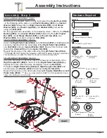
HANDLE BAR ASSEMBLY
Please remove the two
Bolts (#31),
two
Spring
Washers (#43),
two
Arc Washers (#41)
pre-assembled
on
Left Coupler Bar (#05) and Right Coupler Bar (#06).
Set them aside nearby for now.
On the left side, insert
Left Handle Bar (#12)
into the
opening at the tip of
Left Coupler Bar (#05)
. Align the
holes of the
Left Handle Bar (#12)
and
Left Coupler
Bar (#05)
and secure from the side using one
Bolt (#31)
,
one
Spring Washer (#43)
and one
Arc Washer (#41)
.
Then, continue from rear/front with with two
Carriage
Bolts (#21)
, two
Arc Washers (#42)
, two
Spring
Washers (#44)
and two
Cap Nuts (#35) .
Repeat this process on the other side using
Right
Handle Bar (#13)
and
Right Coupler Bar (#06)
.
PULSE HANDLE BAR ASSEMBLY
Install the
Pulse Handle Bar (#14)
onto the bracket
of the
Center Post (#02)
as shown in the illustration
below using two
Bolts (#29)
. Please ensure the wire of
the
Handle Pulse (#52
A
)
is free and clear, avoiding
pinching it during this assembly step.You will need to
connect this wire to the
Monitor (#51
&
)
later.
NUTS
WASHERS
BOLTS
#21. Carriage Bolt (M6x38 mm)
[4 Pieces]
#29. Bolt (M8x30 mm)
[2 Pieces]
#31. Bolt (M8x15 mm) [2 Pieces]
#41. Arc Washer (M8)
[2 Pieces]
#42 Arc Washer (M6)
[4 Pieces]
#43. Spring Washer (M8)
#44. Spring Washer (M6)
[4 PIeces]
#35. Cap Nut (M6)
[4 Pieces]
[2 Pieces]
LEFT
RIGHT
After complete assembly: If the computer is
not picking up your hand pulse signal
(or you are getting
inaccurate readings), Please refer to our “Troubleshooting” section on
Page 21
for other troubleshoot issues.
HAND PULSE SIGNAL
Troubleshooting
Assembly Instructions
Page 10
BRT 3858


