Hardware Required
A s s e m b l y S t e p 7
NUTS
WASHERS
BOLTS
#25. Hex Bolt (M8x60 mm)
[2 Pieces]
#30. Bolt (M8x20 mm)
[2 Pieces]
#39. Washer (M10)
[2 Pieces]
#40. Washer (M8)
[4 Pieces]
#43. Spring Washer (M8)
#50. Lock Knob (M10)
[2 Pieces]
Others
#38. Nylon Nut (M8)
[2 Pieces]
[2 Pieces]
SEAT FRAME ASSEMBLY
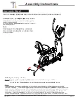
With the help of an assistant, loosen the pre-assembled
Spring
Loaded Knob (#49)
and pull back slightly on it so that you may
proceed to insert the
Seat Post (#09)
into the mouth of the post that
is protruding from the
Main Frame (#01)
down a minimum of four
inches so that the corresponding holes can engage. Screw in the
Spring Loaded Knob (#49)
through the
Main Frame (#01)
and then
through any one of the holes located on the
Seat Post (#09).
Note: The
Spring Loaded Knob (#49)
has a safety feature that
allows you to loosen it by turning it counter-clockwise three times as
you pull it outward. This knob can be loosened to adjust the seat
height. Adjust the seat height and then release the knob back in. Tighten
the knob by turning clockwise. See the more detailed explanation
and illustrations below.
REAR HANDLEBAR ASSEMBLY
Next, with the help of an assistant, align the four of the
Left Rear
Handle Bar (#10)
and
Right Rear Handle Bar (#11)
to the holes on the
Backrest Cushion Frame (#08)
and secure all
using the two
Hex Bolts (#25),
followed by two
Washers (#40),
and
two
Nylon Nuts (#38).
Next, slide the
Seat Cushion Frame (#07)
onto the trough of the
Seat Post (#09)
as shown below. Secure using two
Knobs (#50)
through two
Washers (#39).
Attach the
Backrest Cushion Frame (#08)
to the
Seat Cushion
Frame (#07),
secure by using two
Bolts (#30),
two
Spring Washers
(#43)
and two
Washers (#40).
Assembly Instructions
Page 12
BRT 3858
Spring Loaded Knob Operation
Turn knob counter-clockwise three times.
Pull knob outward and adjust bottom frame
simultaneously.
Push knob back inward until it clicks and then
tighten it by turning clockwise.


