MT2136
5-3
CONVECTION SYSTEM
POSSIBLE CAUSE(S)
SUGGESTED REMEDY
Symptom #1 - Blower motor(s) not running
Blower switch off.
No power to the oven.
Motor fuse blown.
Faulty start capacitor.
Motor burned out.
Thermal overload tripped.
No voltage at the motor contactor coil.
Faulty motor contactor.
Turn switch to on position.
Verify power to the oven. If there is no power deĆ
termine cause.
Replace fuse. Determine the amp draw.
Replace capacitor.
Check draw (3 amps or greater).
Determine if the cooling blower (or fans) are operĆ
ating. If not, verify voltage to the cooling blower.
If voltage is present, replace the cooling blower
motor. If voltage is not present, verify voltage
through the thermal switch. If no voltage is presĆ
ent, replace the thermal switch.
Check for blown fuse or bad blower switch.
Replace motor contactor.
Symptom #2 - Blower motor(s) do not shut off
Faulty motor contactor.
Faulty thermocouple on Hi/Lo board.
Faulty Hi/Lo board.
Hi/Lo board is not adjusted properly.
Replace contactor.
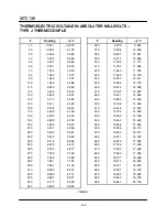
Refer to the chart on page 6-5 of the Technical
Appendix. If the readings do not match replace
the thermocouple.
Determine if 115 VAC is coming out of #7 with the
adjustable potentiometer turned completely
counterĆclockwise. If voltage is still present, reĆ
place the board.
Check and readjust Hi/Lo board. Refer to page
4-4 of Calibration and Adjustment.
Symptom #3 - Blower motor running backward
Motor off by thermal overload (other fans forcing
blower to spin).
Faulty capacitor.
Determine if the cooling blower (or fans) are operĆ
ating. If not, verify voltage to the cooling blower.
If voltage is present, replace the cooling blower
motor. If voltage is not present, verify voltage
through the thermal switch. If no voltage is presĆ
ent, replace the thermal switch.
Replace capacitor.
Summary of Contents for MT2136 Series
Page 4: ...INTRODUCTION CHAPTER 1 ...
Page 15: ...MT2136 1 11 35 30 35 29 39 28 38 33 34 31 37 36 26 27 32 EXTERIOR COMPONENTS FIGURE 3 ...
Page 17: ...MT2136 1 13 CE GAS BURNER COMPONENTS Control Box not Shown 16 17 FIGURE 5 ...
Page 19: ...MT2136 1 15 This page intentionally left blank ...
Page 20: ...ASSEMBLY CHAPTER 2 ...
Page 23: ...MT2136 2 3 This page intentionally left blank ...
Page 24: ...OPERATION CHAPTER 3 ...
Page 49: ...MT2136 3 25 16 17 18 19 20 21 12 13 13 13 4 7 15 3 2 1 14 8 9 10 6 11 5 5 FIGURE 4 ...
Page 50: ...OPERATION 3 26 16 17 20 19 18 15 3 12 13 13 13 4 14 7 1 2 8 9 10 6 11 5 5 FIGURE 5 ...
Page 53: ...MT2136 3 29 1 17 3 2 4 16 16 16 15 21 5 13 14 14 10 18 19 6 7 8 20 9 12 11 FIGURE 8 ...
Page 54: ...OPERATION 3 30 1 18 16 16 16 16 17 15 22 5 3 2 4 13 10 19 20 6 7 8 21 9 12 11 14 14 FIGURE 9 ...
Page 55: ...MT2136 3 31 1 21 21 21 17 16 22 18 20 19 14 3 2 4 11 6 13 12 15 10 7 8 9 5 FIGURE 10 ...
Page 56: ...OPERATION 3 32 1 8 8 8 8 6 7 16 15 17 18 3 2 4 11 5 9 9 12 13 14 FIGURE 11 ...
Page 57: ...MT2136 3 33 1 6 9 8 19 22 21 7 16 17 2 3 4 18 5 10 14 20 12 11 13 15 25 25 25 24 FIGURE 12 ...
Page 58: ...OPERATION 3 34 1 FIGURE 13 ...
Page 60: ...CALIBRATION AND ADJUSTMENT CHAPTER 4 ...
Page 77: ...MT2136 4 17 This page intentionally left blank ...
Page 78: ...TROUBLESHOOTING CHAPTER 5 ...
Page 86: ...TECHNICAL APPENDIX CHAPTER 6 ...


