MT2136
4-15
RERATING THE APPLIANCE
Due to the lack of oxygen at higher elevations, the
unit may need to be rerated. (The orifice size may
need to be adjusted to accommodate different air
pressures at higher elevations.) If not rerated, inĆ
complete combustion may occur releasing AldeĆ
hydes and CO or Carbon Monoxide.
Any of these
are unacceptable and may be hazardous to the
health of the operator.
To choose the correct orifice for different altitudes
several factors must be known:
1. Altitude
2. BTUs per burner
3. Manifold pressure
4. Correct orifice size at sea level
5. BTU value of the gas
The following are generally accepted heating
values:
A.) Natural Gas - 1000 BTU/Cu Ft
B.) Propane - 2550 BTU/Cu Ft
C.) Butane - 3000 BTU/Cu Ft
6. Specific gravity
The following are generally accepted values
(Air = 1.0):
A.) Natural Gas - 0.63
B.) Propane - 1.50
C.) Butane - 2.00
NOTE: For other gases contact your local gas supĆ
plier for values.
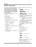
Use the following formulas to calculate the correct
orifice:
1. Firing rate
# of burners
=ąBTU per burner
2. BTU per burner
Heating value of Gas
=ąCuFt/hr
3. CuFt/Hr
Specific Gravity Multiplier
=ąEquiv. CuFt/hr
4. Use TABLE FĆ1 from the National Fuel Gas
Code Handbook to determine the proper oriĆ
fice size at sea level.
NOTE: The sea level orifice size is needed to
determine the proper orifice at any
elevation.
5. Use TABLE FĆ4 from the National Fuel Gas
Code Handbook to determine the correct oriĆ
fice for the applicable elevation.
6. Use TABLE FĆ3 from the National Fuel Gas
Code Handbook to determine the specific
gravity multiplier.
EXAMPLE
Known factors:
1. Altitude = 5000 ft.
2. BTUs per appliance = 55,000
3. Number of burners = 2
4. BTU value of the gas = 900
5. Specific gravity = .50
Calculations:
1. 55,000
2
=ą27,500 BTU per burner
2. 27,500
900
=ą30.55 CuFt/hr
3. 30.55
1.10
=ą27.77 Equiv. CuFt/hr
Using the tables in the National Fuel Gas Code
Handbook we can determine that:
1. Correct orifice size at sea level = #40
2. Correct orifice size at 5000 ft = #42
Summary of Contents for MT2136 Series
Page 4: ...INTRODUCTION CHAPTER 1 ...
Page 15: ...MT2136 1 11 35 30 35 29 39 28 38 33 34 31 37 36 26 27 32 EXTERIOR COMPONENTS FIGURE 3 ...
Page 17: ...MT2136 1 13 CE GAS BURNER COMPONENTS Control Box not Shown 16 17 FIGURE 5 ...
Page 19: ...MT2136 1 15 This page intentionally left blank ...
Page 20: ...ASSEMBLY CHAPTER 2 ...
Page 23: ...MT2136 2 3 This page intentionally left blank ...
Page 24: ...OPERATION CHAPTER 3 ...
Page 49: ...MT2136 3 25 16 17 18 19 20 21 12 13 13 13 4 7 15 3 2 1 14 8 9 10 6 11 5 5 FIGURE 4 ...
Page 50: ...OPERATION 3 26 16 17 20 19 18 15 3 12 13 13 13 4 14 7 1 2 8 9 10 6 11 5 5 FIGURE 5 ...
Page 53: ...MT2136 3 29 1 17 3 2 4 16 16 16 15 21 5 13 14 14 10 18 19 6 7 8 20 9 12 11 FIGURE 8 ...
Page 54: ...OPERATION 3 30 1 18 16 16 16 16 17 15 22 5 3 2 4 13 10 19 20 6 7 8 21 9 12 11 14 14 FIGURE 9 ...
Page 55: ...MT2136 3 31 1 21 21 21 17 16 22 18 20 19 14 3 2 4 11 6 13 12 15 10 7 8 9 5 FIGURE 10 ...
Page 56: ...OPERATION 3 32 1 8 8 8 8 6 7 16 15 17 18 3 2 4 11 5 9 9 12 13 14 FIGURE 11 ...
Page 57: ...MT2136 3 33 1 6 9 8 19 22 21 7 16 17 2 3 4 18 5 10 14 20 12 11 13 15 25 25 25 24 FIGURE 12 ...
Page 58: ...OPERATION 3 34 1 FIGURE 13 ...
Page 60: ...CALIBRATION AND ADJUSTMENT CHAPTER 4 ...
Page 77: ...MT2136 4 17 This page intentionally left blank ...
Page 78: ...TROUBLESHOOTING CHAPTER 5 ...
Page 86: ...TECHNICAL APPENDIX CHAPTER 6 ...


